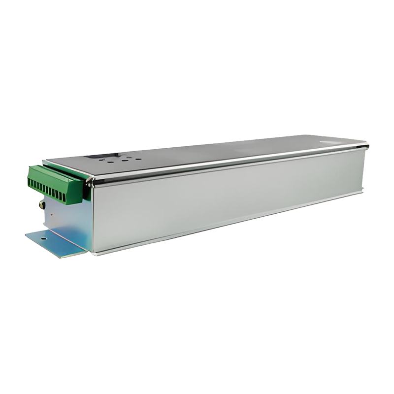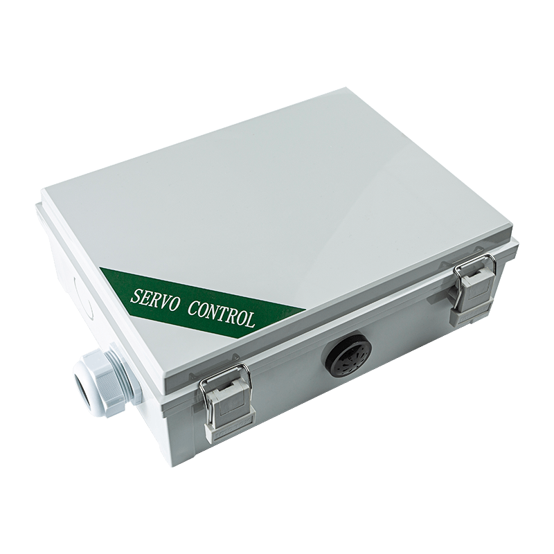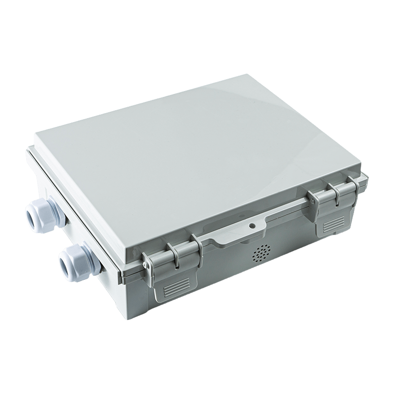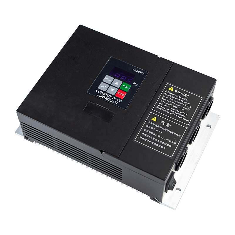


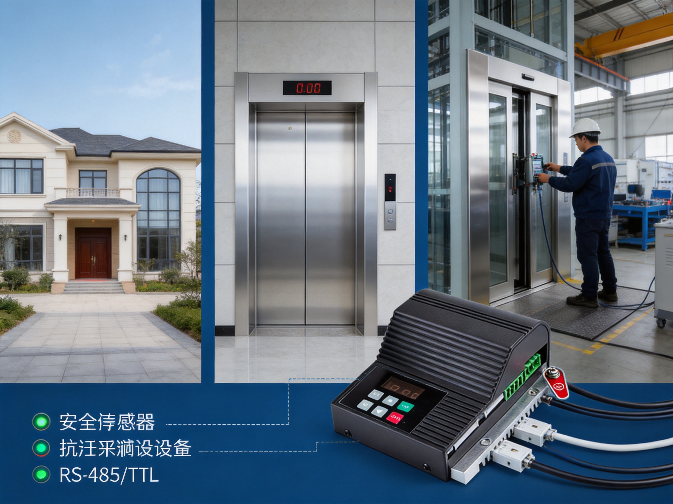
Elevator door performance has a direct influence on passenger safety, ride comfort, system availability, and the overall service life of an elevator installation. A door system must open and close smoothly, respond accurately to commands, protect passengers from obstruction, and continue operating reliably under frequent daily cycling. These requirements become even more demanding in export elevator projects, villa elevators, customized door operator systems, and installations where the available commissioning time is limited.
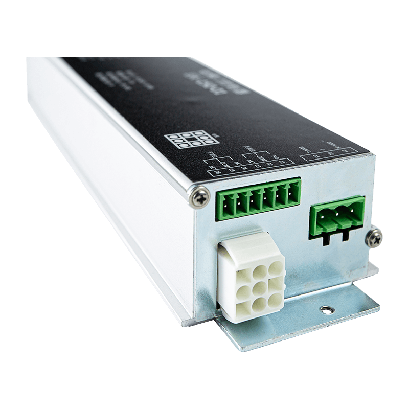
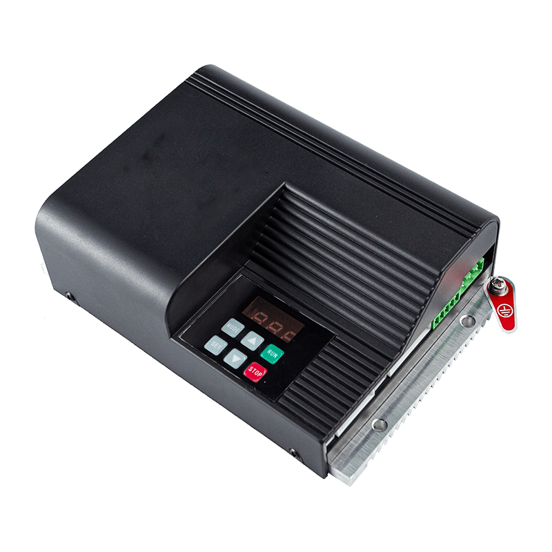
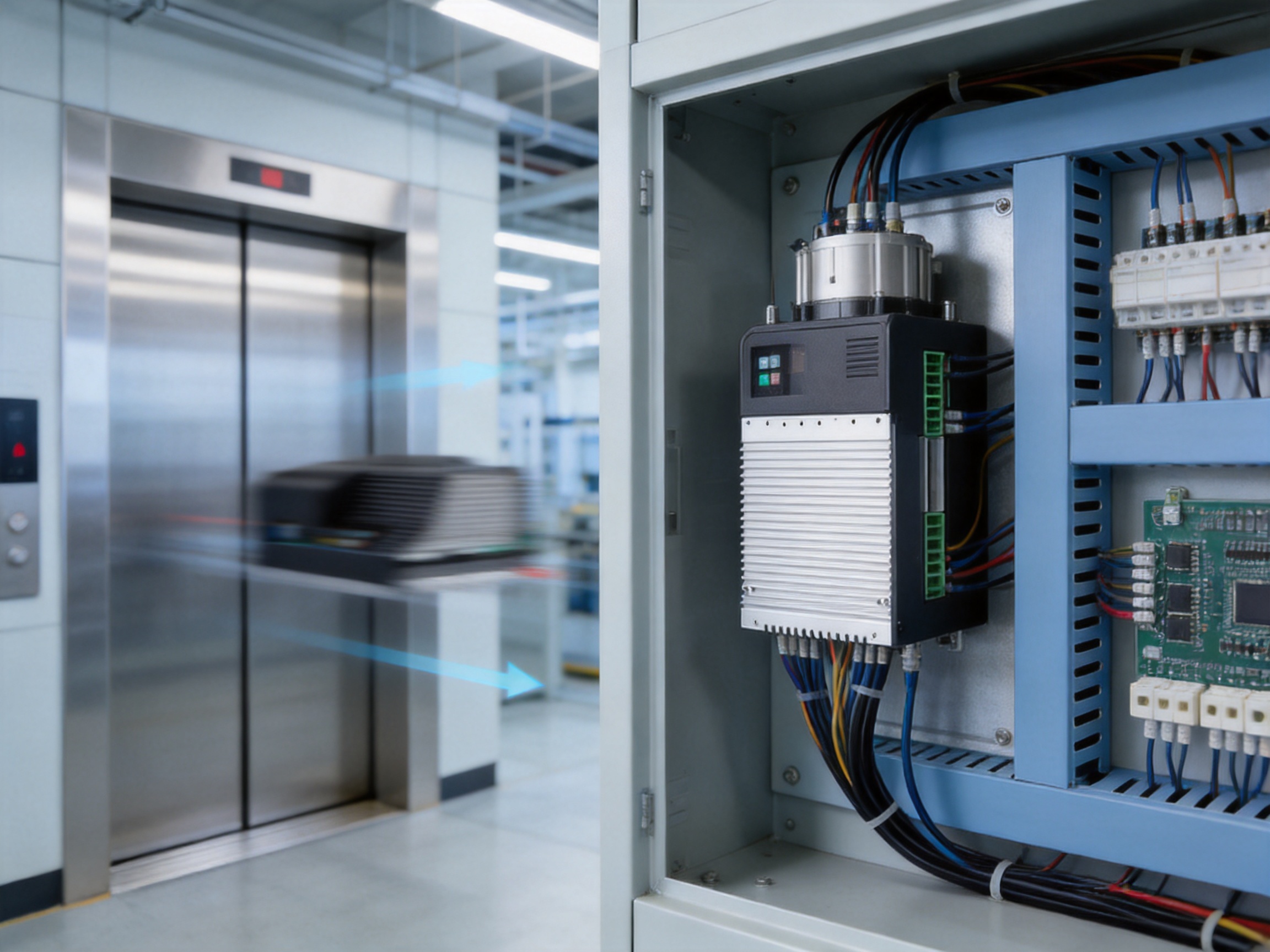
The Elevator Door Controller AIG-500E-01 is designed to address these challenges through closed-loop servo control, flexible parameter management, integrated monitoring, versatile input and output functions, and support for modern communication and commissioning methods. It is a high-performance lift door servo controller intended for the precision management of sliding elevator doors. By combining a fully closed-loop space vector PWM control method with encoder-based feedback, the controller can regulate motor operation more accurately than basic open-loop drive solutions.
The controller is compatible with the MT01-TB-120W permanent magnet servo motor and can also support controllable 24V DC brushless or servo motors within its rated output capacity. Its single-phase 176–264V AC input, integrated 24V switching power supply, eight digital inputs, three relay outputs, and RS-485 communication function make it suitable for both standalone door operator systems and integrated elevator control architectures.
Beyond its electrical specifications, the product is supported by a manufacturer focused on industrial sensing, intelligent connectivity, edge-layer hardware, and industrial data integration. This combination of product engineering and industrial application knowledge helps provide a practical solution for customers seeking more than a basic motor controller. The result is a door control platform that supports precise operation, simplified setup, detailed diagnosis, and future-oriented equipment integration.
Elevator Door Controller
1. The Role of a Dedicated Elevator Door Controller
An elevator door controller is responsible for converting commands from the elevator control system into carefully controlled mechanical movement. It manages the motor during opening, closing, acceleration, deceleration, stopping, holding, and reversal. At the same time, it must interpret signals from safety devices, fire protection circuits, arrival sensors, and other parts of the elevator system.
Door operation is not simply a matter of turning a motor on or off. A suitable controller must coordinate speed and position throughout the entire travel distance. The door should move rapidly through the main portion of its travel while reducing speed before reaching the fully open or fully closed position. If the door approaches the end position too quickly, it may create impact, noise, vibration, or mechanical stress. If it moves too slowly throughout the complete cycle, passenger flow and elevator availability may suffer.
The AIG-500E-01 addresses this challenge by allowing the technician to configure multiple speed gears, buffer distances, acceleration values, and deceleration values for both opening and closing. This provides the flexibility needed to match the control profile to different door weights, travel distances, mechanical arrangements, and passenger-use requirements.
The controller also supports safety-related input signals, including anti-pinch and fire protection functions. When the control system receives an appropriate signal, it can respond according to the configured logic and operating mode. Adjustable judgment times for door blocking help technicians balance rapid protection response with the practical need to avoid false triggering caused by temporary mechanical resistance or signal fluctuations.
In this way, the controller serves as the intelligence layer between the elevator control system, the motor, the encoder, the door mechanism, and the safety-related field signals. Its performance directly affects the smoothness, repeatability, and maintainability of the entire door operator system.
2. Core Control Technology
2.1 Fully Closed-Loop Space Vector PWM
The AIG-500E-01 uses fully closed-loop space vector PWM control. Space vector pulse-width modulation enables the controller to manage the motor’s electrical output with a high degree of precision. Instead of relying only on a predetermined voltage and frequency relationship, the controller continuously regulates the motor based on operating conditions and feedback information.
The closed-loop architecture is especially valuable in elevator door applications because the mechanical load may change during operation. Door panels can experience variations caused by guide rail resistance, belt tension, temperature, installation alignment, passenger contact, or gradual mechanical wear. Feedback allows the controller to compensate more effectively for these changes and maintain a more stable motion profile.
Compared with a simple open-loop controller, a closed-loop system can provide more reliable position control and better stopping repeatability. It can also support smoother transitions between speed stages. These benefits are important at the beginning and end of travel, where small differences in speed or position can have a noticeable effect on noise, vibration, and perceived quality.
2.2 Encoder-Based Position Management
The controller includes technician parameters for configuring motor pole pairs and encoder lines. These parameters allow the drive to interpret feedback correctly for the connected motor and encoder combination. Accurate encoder configuration is fundamental to the controller’s ability to determine door movement and regulate the motor.
With appropriate encoder settings, the controller can track the door position during operation and use that information to manage acceleration, constant-speed travel, deceleration, and final stopping. This supports repeatable door positioning and helps the system recognize whether the door has reached its open or closed target.
The use of configurable encoder-related parameters also provides greater adaptability than a controller designed for only one fixed motor configuration. While the AIG-500E-01 is specifically designed to work with the MT01-TB-120W permanent magnet servo motor, its stated compatibility with controllable 24V DC brushless and servo motors gives system integrators additional options within the rated electrical limits.
2.3 Motor Output Capacity
The controller provides a maximum output current of 7.5A and a maximum output power of 150W. This capacity is suited to compact elevator door operator systems requiring controlled movement rather than high-power traction. Its application range includes export elevator doors, villa elevator doors, and specially customized door operator systems.
The integrated 24V switching power supply simplifies the system architecture. Instead of requiring a separate low-voltage supply for compatible control components, the controller can provide an integrated source for relevant system functions. This can reduce wiring complexity, simplify cabinet layout, and make installation more convenient when the connected equipment is designed for the available supply.
3. Electrical Design and System Compatibility
The AIG-500E-01 operates from a single-phase input of 176–264V AC at 50 or 60Hz. This input range supports deployment in electrical environments where nominal voltage conditions may vary. It is suitable for a broad range of commercial, residential, and export elevator installations that use compatible single-phase power.
Single-phase operation is practical for many elevator door operator applications because the door controller does not generally require the same power architecture as the main elevator traction system. The controller can be installed as a dedicated door control unit while receiving command and safety signals from the broader elevator control system.
System compatibility is strengthened by the controller’s support for TTL communication for data copying and external parameter setting or debugging. The RS-485 networking function adds another communication option for integration, service, and system-level information exchange. These interfaces can be valuable when manufacturers, installers, or maintenance teams need to transfer settings, connect service tools, or incorporate the controller into a wider equipment network.
Communication functions are increasingly important in modern equipment because installation and maintenance teams need faster access to operating information. A controller that can expose parameters and support digital configuration can reduce reliance on repeated manual adjustments. It may also help standardize settings across multiple elevator units in the same project.
The product’s compatibility with both conventional control signals and communication-based commissioning makes it practical for different project structures. A simple installation may use discrete open, close, safety, and arrival signals. A more advanced installation can combine these field signals with parameter tools, TTL data transfer, and RS-485 networking.
4. Comprehensive Operating Monitoring
A built-in digital display allows technicians to monitor several important operating values. The display can track output speed, output current, busbar voltage, door position, and total run time. These values provide a useful picture of both immediate operating status and accumulated equipment use.
Output speed helps technicians evaluate whether the door is following the intended motion profile. If the door moves too slowly, accelerates unexpectedly, or fails to reach a configured speed stage, the display can assist with troubleshooting. Output current provides an indication of motor loading. Abnormally high current may suggest mechanical resistance, incorrect parameters, misalignment, excessive belt tension, or another condition requiring attention.
Busbar voltage information helps technicians understand the controller’s internal power condition. Door position is essential for verifying whether the system is reaching the expected open and closed locations. Total run time provides a basic reference for maintenance planning and equipment usage evaluation.
Compared with a controller that provides little or no local information, an integrated display can reduce troubleshooting time. Technicians do not need to depend entirely on external instruments or guesswork during initial setup. This is especially useful in field environments where access to advanced test equipment may be limited.
The display also supports clearer communication between installers and service personnel. A technician can record visible values during commissioning, compare values before and after an adjustment, and identify whether a problem is electrical, mechanical, or parameter-related. Better visibility can contribute to shorter service interruptions and more consistent installation quality.
5. One-Key Commissioning and Door Learning
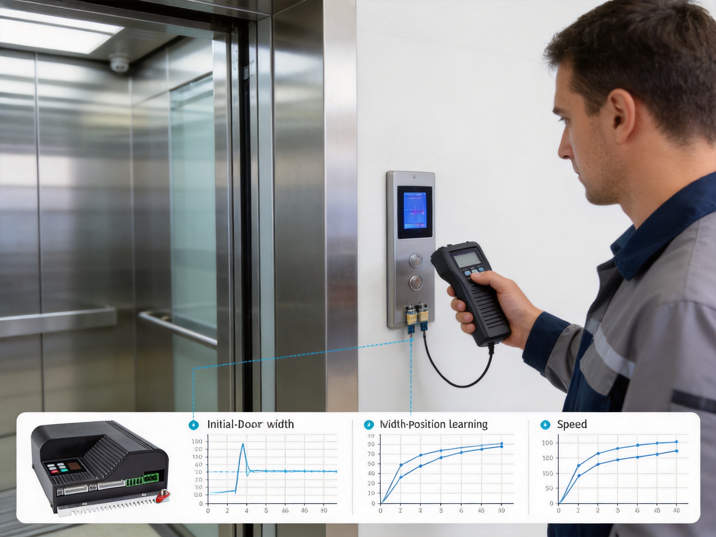
One of the controller’s practical features is the automated “one-key debugging” function identified as A-c. This function can measure door width and test the initial position. Automated learning is valuable because door travel distance and initial positioning must be established accurately before the system can apply the intended speed and stopping profile.
Traditional commissioning may require repeated manual movement, measurement, parameter entry, and adjustment. This process can be time-consuming, particularly when many elevator units must be commissioned in one project. It may also create inconsistency if different technicians use slightly different procedures.
One-key commissioning helps simplify this stage by allowing the controller to perform an organized learning sequence. Once the mechanical system and motor are correctly installed, the technician can initiate the function and allow the controller to establish essential travel information. The technician can then review the results and fine-tune the door curves where necessary.
This does not eliminate the need for proper installation inspection. The door panels, guide rails, belts, motor connection, encoder wiring, safety circuits, and mechanical clearances must still be checked carefully. However, automated measurement can reduce repetitive setup work and provide a more structured starting point for final adjustment.
For elevator manufacturers and integrators, the one-key function can improve production efficiency. A repeatable commissioning process helps reduce variation between units and may shorten the time required for factory testing or on-site handover. For service organizations, it can make replacement controller setup more straightforward when the mechanical configuration is known and suitable.
6. Flexible Door Curve Configuration
The controller provides separate parameter groups for door curves, identified as the O and C groups. These groups allow technicians to configure four different speed gears together with buffer distances, acceleration values, and deceleration values for opening and closing cycles.
Opening and closing do not always require identical control profiles. The door may experience different mechanical loads in each direction. Closing may require more careful low-speed control because of passenger safety and anti-pinch considerations. Opening may require efficient acceleration to clear the entrance quickly during passenger boarding. Separate settings allow the technician to optimize both directions rather than applying one compromise profile.
Four speed gears provide a useful balance between smooth motion and fast operation. A typical profile may include an initial acceleration stage, a higher-speed travel stage, an intermediate reduction stage, and a low-speed final approach. The exact profile depends on the door mechanism and project requirements, but the controller provides the parameter structure needed to create a tailored sequence.
Buffer distance settings determine when the controller begins reducing speed before reaching the target position. If the buffer distance is too short, the door may approach the end position aggressively. If it is too long, the door may spend excessive time at low speed. Adjustable acceleration and deceleration values provide additional control over comfort, noise, mechanical loading, and cycle time.
This level of parameterization is a significant advantage over basic controllers with only a small number of fixed adjustment points. A fixed profile may perform adequately on one door system but require compromises on another. A configurable profile allows installers to adapt the controller to different panel weights, door widths, belt arrangements, and mechanical conditions.
6.1 Opening Control
During opening, the controller can use the configured opening curve to accelerate the door smoothly, maintain efficient travel speed, and reduce speed before the fully open position. The final approach can be tuned to limit impact and reduce mechanical vibration.
A well-adjusted opening curve contributes to passenger comfort and perceived product quality. Doors that start with a sudden jerk or stop harshly can create an impression of poor construction even when the elevator’s major systems are functioning correctly. Smooth control also reduces stress on door rollers, guide components, belts, couplings, and mounting structures.
6.2 Closing Control
Closing control requires careful coordination between speed, position, safety signals, and anti-pinch logic. The controller can apply a separate closing curve with its own speed gears, acceleration, deceleration, and buffer distance settings. This provides the technician with more control over the final closing movement.
The system supports level and edge switching gate signal modes. This flexibility allows the controller to match different elevator control architectures. Adjustable judgment times for door blocking also help configure how the system interprets resistance or obstruction during operation.
Correct parameter selection remains essential. The final settings should be validated with the actual door mechanism and relevant safety procedures. The controller provides the adjustment capability, while the installer must ensure that the complete elevator door system complies with applicable requirements.
7. I/O Architecture for Elevator Applications
The AIG-500E-01 includes eight digital inputs. These inputs can receive signals such as fire alarms, safety sensor conditions, door commands, arrival signals, and motor thermal protection. Providing multiple dedicated inputs gives the controller the flexibility needed for different elevator system designs.
Digital input capacity is important because elevator doors interact with several control and safety devices. An open command may come from the elevator controller, while a close command may be generated after the configured dwell period. Anti-pinch or safety sensor signals may require the door to stop, reopen, or change behavior. A fire protection signal may invoke a special operating response. An arrival signal may indicate that the elevator has reached the designated floor and that door operation is permitted.
The controller also supports motor thermal protection input. Thermal protection helps respond to abnormal motor temperature conditions or signals from an associated protection device. This is important in systems that operate frequently or experience unusual mechanical resistance. Detecting thermal conditions can help prevent damage and support safer maintenance decisions.
Three relay outputs are available for open position reached, close position reached, and fault alarm signals. These outputs allow the controller to communicate status conditions to an external elevator control system, monitoring panel, or diagnostic circuit.
Open and close position signals provide confirmation that the door has reached the relevant target. A fault alarm output can notify the wider system when the controller detects an abnormal condition. By providing both inputs and outputs, the product can participate in a two-way equipment control structure rather than operating as an isolated motor drive.
8. Safety-Oriented Operating Functions
Elevator doors are safety-critical moving assemblies. The controller therefore must support predictable behavior when commands change, safety signals activate, or the door encounters resistance. The AIG-500E-01 includes functions intended to help coordinate anti-pinch, fire protection, door blocking judgment, position detection, and fault alarm signaling.
The anti-pinch and fire protection input allows the controller to receive safety-related instructions from external devices. Depending on the configured operating logic and the overall elevator design, these signals can influence the door’s movement. The controller’s role is to process the electrical signal and apply the configured response consistently.
Level and edge switching gate signal modes provide additional flexibility. In level mode, the controller may interpret the continued presence of a signal as an active command. In edge mode, it may respond to a signal transition. The correct choice depends on the signal source and the design of the host elevator control system.
Adjustable door-blocking judgment time is another useful function. Mechanical systems can experience brief resistance during normal movement. If the judgment time is set too short, temporary resistance may be treated as a blockage. If it is set too long, the system may respond slowly to a genuine obstruction. The ability to adjust this parameter helps technicians match the controller to the actual mechanical behavior of the door.
Safety performance depends on the complete elevator system, including mechanical construction, safety sensors, control logic, wiring, installation, inspection, and maintenance. The controller supports these functions but does not replace the need for a properly designed and compliant elevator safety system.
9. Specialized Modes and Communication Functions
The AIG-500E-01 includes a demo mode identified as F1.4. This mode is intended for continuous test cycling of the door mechanism. Repeated cycling can be useful during demonstration, factory inspection, endurance observation, and maintenance testing.
A continuous test mode allows installers to observe the door through repeated opening and closing sequences without manually issuing every command. It can help identify inconsistent stopping, unusual sound, mechanical interference, temperature rise, loose connections, or parameter problems that may not appear during a single cycle.
Test cycling should always be performed under controlled conditions. The door area must be secured, and personnel must remain clear of moving components. The technician should monitor the mechanism and stop the test if abnormal behavior is observed.
TTL communication supports data copying and external parameter setting or debugging. This can simplify the transfer of configuration information and help service personnel work with the controller using external tools. RS-485 communication networking provides another option for integration with connected devices and service infrastructure.
Communication support becomes increasingly useful as elevator systems become more connected. In a multi-unit building or manufacturing project, service personnel may need to compare parameters across several controllers. Digital communication can make this process more efficient than inspecting every value manually on a local display.
10. Advantages Compared with Basic or Less Flexible Controllers
When evaluating an elevator door controller, buyers often compare products based on more than motor output. The controller’s commissioning process, feedback accuracy, I/O capacity, diagnostic visibility, communication support, and ability to adapt to different door mechanisms can have a major effect on project cost and long-term reliability.
10.1 More Accurate Motion Management
The fully closed-loop space vector PWM architecture gives the AIG-500E-01 an advantage over simple open-loop solutions. Feedback-based control can improve position repeatability and help the controller compensate for variations in mechanical load. This is particularly relevant to doors that operate many times each day.
10.2 More Detailed Adjustment Capability
Some basic door controllers offer only a limited number of speed and timing parameters. The AIG-500E-01 provides four speed gears, buffer distances, acceleration and deceleration settings, separate opening and closing curve groups, motor parameters, encoder parameters, signal modes, and blocking judgment time. This broader adjustment range gives the installer more opportunity to optimize the door rather than accepting a generic profile.
10.3 Faster Commissioning
The one-key debugging function can reduce the manual effort required to measure door width and test the initial position. This can be especially valuable for elevator manufacturers and installation companies managing multiple units. A more repeatable process may reduce commissioning errors and shorten the time required before final handover.
10.4 Better Local Diagnostics
The digital display provides access to output speed, current, busbar voltage, door position, and total run time. This gives technicians more information than a controller that provides only a basic fault indicator. Better diagnostic visibility can help distinguish between electrical loading, position problems, configuration issues, and mechanical resistance.
10.5 Broader Integration Options
Eight digital inputs, three relay outputs, TTL communication, and RS-485 networking enable the controller to connect with a wide range of elevator control systems and service tools. This makes the product suitable for both straightforward installations and customized system designs.
10.6 Practical Motor and Power Compatibility
Support for the MT01-TB-120W permanent magnet servo motor provides a defined motor pairing for system designers. At the same time, compatibility with controllable 24V DC brushless or servo motors within a maximum output current of 7.5A and maximum output power of 150W provides additional flexibility for qualified applications.
11. Manufacturing and Engineering Strengths
The controller is produced by a high-tech enterprise whose broader capabilities include data sensing, intelligent connectivity, edge-layer hardware, and industrial data integration. These capabilities are relevant to the manufacturing of industrial control equipment because a reliable controller requires coordination between electrical design, embedded control, communications, production testing, and application support.
A modern industrial electronics manufacturing process typically begins with controlled product design and component selection. The electrical architecture must account for the input voltage range, motor output, switching power supply, communication interfaces, digital inputs, relay outputs, and display functions. Components must be selected according to electrical stress, temperature, switching frequency, expected operating cycles, and the installation environment.
For a door controller, the manufacturing process must also protect signal quality. Encoder signals, TTL communication, RS-485 communication, digital inputs, and motor drive outputs operate in an environment where electrical noise may be generated by switching devices and motor currents. Good product engineering therefore requires attention to circuit layout, grounding strategy, signal separation, connector design, and protective measures.
Production quality is also influenced by process consistency. Printed circuit board assembly, soldering, connector installation, enclosure assembly, firmware loading, parameter initialization, and functional testing must be performed in an organized manner. A controller may contain high-voltage input sections, low-voltage control circuits, communication interfaces, and motor output stages. Each section requires appropriate inspection and testing before release.
The company’s focus on industrial data sensing and intelligent connectivity supports a product development approach that recognizes the needs of real equipment environments. The AIG-500E-01 is not merely a laboratory drive. It is designed for an application in which technicians need clear operating information, installers need efficient commissioning, and system integrators need multiple signal and communication options.
11.1 Application-Oriented Product Development
Application-oriented development means that product functions are selected according to real installation and maintenance requirements. The digital display, one-key commissioning, configurable door curves, thermal protection input, relay status outputs, and demo mode all reflect practical elevator door service needs.
This approach can provide an advantage over products designed only around a motor-control core. A technically capable motor drive may still be difficult to apply if it lacks door-specific parameters, position learning, safety-related inputs, or accessible diagnostics. By integrating these functions into one product, the controller can reduce the amount of additional equipment and custom programming required by the system integrator.
11.2 Integration of Hardware and Data Functions
The company’s expertise in edge-layer hardware and industrial data integration is also relevant to the controller’s communication capabilities. In industrial environments, equipment increasingly needs to provide information beyond simple start and stop commands. Operating values, fault states, position status, and parameter data can support more efficient service and equipment management.
Although the AIG-500E-01 is primarily a door motion controller, its display and communication interfaces create a foundation for more connected maintenance practices. Data can be reviewed locally, transferred through supported communication methods, or incorporated into a larger service process where appropriate.
11.3 Support for Custom Applications
Elevator projects can differ substantially. Export markets may use different electrical conditions, signal conventions, door sizes, motor arrangements, and commissioning practices. Villa elevators may prioritize compact equipment and quiet movement, while customized door operator systems may require special signal logic or parameter settings.
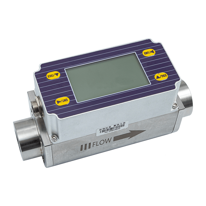
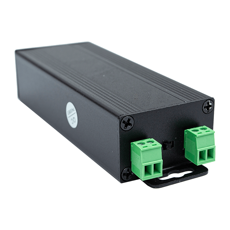
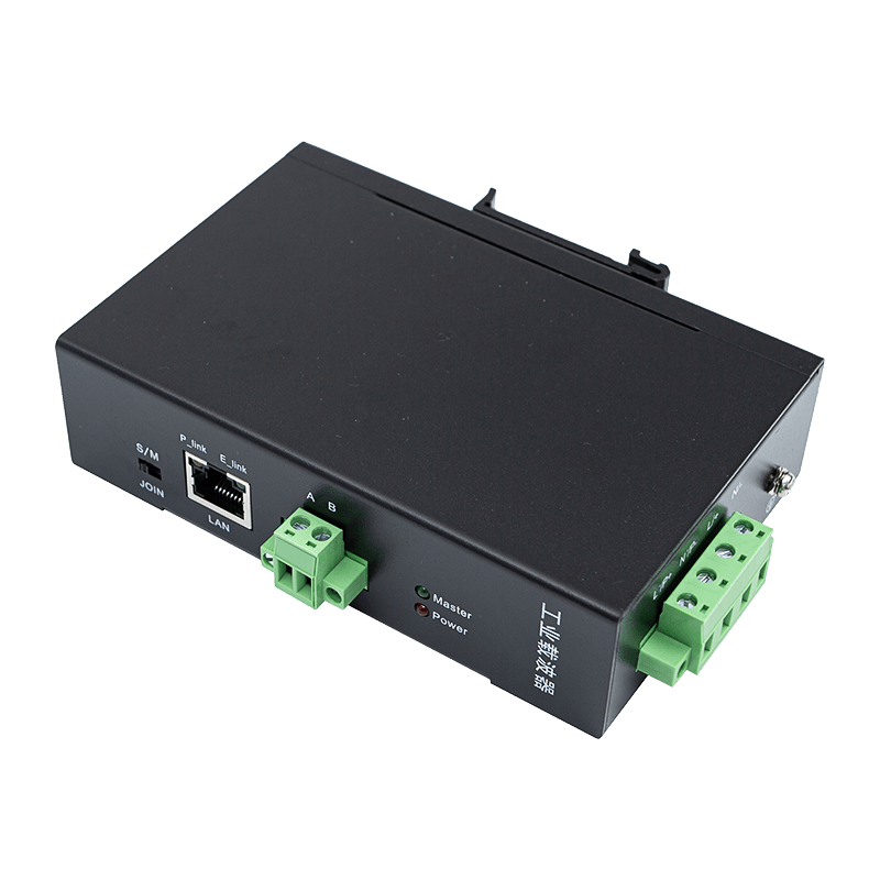
The controller’s broad parameter structure and flexible I/O make it more suitable for such variation than a narrowly fixed product. The manufacturer’s experience across industrial transmitters, flow meters, wireless temperature monitoring systems, power line communication products, and automatic door controllers also indicates a wider understanding of industrial application requirements.
Customers can benefit from working with a supplier that develops multiple categories of sensing, connectivity, and automation products. Such a supplier is more likely to understand system-level issues including signal compatibility, equipment networking, industrial data collection, and field commissioning.
12. Installation and Commissioning Considerations
Successful use of the AIG-500E-01 begins with correct mechanical and electrical preparation. The door panels should move freely by hand within the permitted installation procedure. Guide rails, rollers, belts, pulleys, couplings, and motor mounts should be aligned and secured. Excessive friction or mechanical interference should be corrected before controller adjustment begins.
The input power must be within the specified 176–264V AC range and must be connected according to the applicable electrical design. Motor wiring, encoder wiring, control inputs, relay outputs, TTL communication, and RS-485 communication should be separated and terminated correctly. The technician should verify polarity, shielding, grounding, and connector seating before energizing the system.
After the initial power-up, the technician should confirm the motor direction and encoder response. Incorrect direction or feedback configuration can cause the door to move unexpectedly. Motor pole pairs and encoder line parameters should be set according to the connected motor and encoder specifications.
The one-key debugging function can then be used to measure door width and test the initial position. After the learning sequence, the technician should observe several complete cycles. Opening and closing curves can be adjusted based on actual movement. The goal is to achieve smooth acceleration, stable travel, controlled deceleration, accurate final positioning, and appropriate response to external commands.
Technicians should also test the open and close position relay outputs, fault alarm output, safety-related input signals, arrival signal, motor thermal protection input, and configured gate signal mode. The anti-pinch and fire protection functions must be verified as part of the complete elevator safety commissioning procedure.
The demo mode can be used for repeated test cycles after initial parameters are established. During this process, technicians should monitor output current, door position, speed behavior, and any abnormal noise or vibration. The total run time display can provide a reference for future maintenance records.
13. Maintenance and Troubleshooting Value
Regular maintenance is necessary for any elevator door system, regardless of controller quality. Mechanical parts can wear, belts can lose tension, rollers can develop resistance, and sensors or wiring can become damaged. A controller with accessible operating data can help maintenance personnel identify changes before they become major failures.
For example, a gradual increase in output current may indicate increasing mechanical resistance. A change in final door position may suggest encoder problems, loose mechanical components, or altered parameter settings. Inconsistent door speed may point to a motor, feedback, wiring, or control profile issue. Busbar voltage information can help identify power-related conditions.
When a fault occurs, the technician should first review the visible operating information and the external signal conditions. The input command, safety signal, position feedback, motor thermal condition, and relay alarm state should be considered together. Troubleshooting should not focus only on the controller because elevator door behavior results from the interaction of electrical and mechanical components.
The controller’s communication functions may also support more efficient service procedures. Parameter data can be copied or externally configured through supported interfaces, reducing the possibility of manual transcription errors. For systems with multiple identical elevator units, standardized parameter management can simplify replacement and maintenance work.
A good maintenance record should include the controller model, connected motor, key motor and encoder parameters, door curve settings, input logic, test results, and any changes made during service. Keeping this information available helps future technicians understand the intended system configuration.
14. Typical Application Scenarios
14.1 Export Elevator Doors
Export elevator projects may involve different electrical standards, installation practices, and service resources. The wide single-phase input range, configurable parameters, communication functions, and local display make the controller suitable for projects requiring flexible commissioning and practical field diagnostics.
14.2 Villa Elevators
Villa elevators often place strong emphasis on quiet operation, smooth movement, compact integration, and reliable service. Closed-loop control and adjustable door curves can help optimize the door mechanism for comfort and reduced mechanical impact. The controller’s integrated power supply and compact functional architecture may also simplify system design where equipment space is limited.
14.3 Customized Door Operator Systems
Customized systems may use special door widths, motor combinations, signal arrangements, or control sequences. The AIG-500E-01 provides configurable motor parameters, encoder settings, speed stages, signal modes, input functions, and relay outputs that can support such projects when the application remains within the product’s electrical and mechanical ratings.
14.4 Factory Testing and Demonstration
The demo mode and display functions are useful during manufacturing inspection and customer demonstrations. Repeated door cycles can help verify the mechanical assembly, while visible speed, current, position, and voltage information can support a more transparent evaluation.
15. Product Performance Parameters
Parameter |
Specification |
Application Value |
Input voltage |
176–264 VAC, 50/60 Hz |
Supports compatible single-phase elevator door installations |
Motor compatibility |
MT01-TB-120W permanent magnet servo motor; controllable 24V DC brushless or servo motor |
Provides a defined motor pairing and application flexibility |
Maximum output current |
7.5A |
Suitable for the specified door operator motor range |
Maximum output power |
150W |
Supports compact elevator door mechanisms within the rated load |
Integrated supply |
24V switching power supply |
Helps simplify low-voltage system integration |
Communication |
RS-485 networking and TTL communication |
Supports networking, data copying, parameter setting, and debugging |
Digital inputs |
Eight |
Accepts open, close, safety, fire protection, arrival, and thermal signals |
Relay outputs |
Three |
Provides open position, close position, and fault alarm status |
Control method |
Fully closed-loop space vector PWM |
Supports precise motor and door motion regulation |
Commissioning function |
One-key debugging, A-c |
Measures door width and tests the initial position |
Special mode |
Demo mode, F1.4 |
Enables continuous test cycling of the door mechanism |
16. Why Choose This Controller for New Projects?
For a new elevator door project, the most important question is not simply whether a controller can make the motor move. The more important question is whether the controller can provide predictable performance throughout installation, commissioning, normal operation, maintenance, and future system development.
The AIG-500E-01 offers a balanced combination of motion control, safety-related signal handling, commissioning assistance, parameter flexibility, local monitoring, and communication capability. This reduces the need to combine a basic motor drive with multiple external devices for functions that are already relevant to elevator door operation.
Its closed-loop control can support smoother and more repeatable movement. Its adjustable door curves can help technicians match performance to the mechanical system. Its one-key commissioning function can reduce setup effort. Its display can improve visibility during troubleshooting. Its I/O structure can accommodate common elevator signals. Its communication interfaces can support data transfer, external debugging, and networking.
These features can help lower the total effort associated with installation and service. The value of a controller should be evaluated over its complete service life, including the time required to configure, inspect, troubleshoot, replace, and maintain the unit. A product that provides more useful information and more adaptable settings may offer advantages even when its initial purchase price is compared with simpler alternatives.
17. Recommended Selection Checklist
Before selecting the controller for a specific elevator door system, the project engineer should confirm the motor type, rated voltage, rated current, output power, encoder specifications, door travel distance, door weight, control signal structure, and required safety interfaces.
The engineer should also confirm that the mechanical door system can operate within the controller’s adjustment range. The maximum output current of 7.5A and maximum output power of 150W must not be exceeded. The selected motor and encoder must be compatible with the controller’s electrical and feedback requirements.
The input and output signal list should be compared with the elevator control cabinet design. If the project requires special signal logic, the level or edge switching mode and the available digital inputs should be reviewed in advance. If system networking is required, the RS-485 and TTL communication functions should be evaluated against the project’s communication architecture.
Finally, the installer should consider the availability of commissioning personnel, service tools, parameter documentation, and maintenance procedures. A controller with extensive functions provides the greatest benefit when technicians are trained to use its display, parameters, learning functions, and diagnostic information correctly.
18. Questions and Answers
Q1: What type of equipment is the AIG-500E-01?
The AIG-500E-01 is a high-performance elevator door servo controller designed to manage sliding lift and elevator doors. It controls the connected motor, manages door movement profiles, processes external commands and safety-related signals, and provides status and diagnostic information.
Q2: Which motor is the controller designed to use?
The controller is specifically designed to work with the MT01-TB-120W permanent magnet servo motor. It also supports controllable 24V DC brushless or servo motors within its maximum rated output current of 7.5A and maximum output power of 150W.
Q3: What input power does the controller require?
It operates from a single-phase input of 176–264V AC at 50 or 60Hz. The application should be checked to ensure that the available power supply is compatible with this range.
Q4: What does fully closed-loop control provide?
Fully closed-loop space vector PWM control uses feedback to regulate motor operation and door position. It can improve movement accuracy, stopping repeatability, and response to changes in mechanical load compared with basic open-loop control methods.
Q5: What is the one-key debugging function?
The one-key debugging function, identified as A-c, automatically measures door width and tests the initial position. It helps establish basic travel information during commissioning and can reduce repetitive manual adjustment.
Q6: Can opening and closing movements be adjusted separately?
Yes. The controller provides separate opening and closing door curve groups, identified as the O and C groups. Technicians can configure speed gears, buffer distances, acceleration, and deceleration for each direction.
Q7: What signals can be connected to the digital inputs?
The digital inputs can be used for open commands, close commands, anti-pinch and fire protection signals, arrival signals, motor thermal protection, and other compatible control functions defined by the installation design.
Q8: What information can be viewed on the digital display?
The display can track output speed, output current, busbar voltage, door position, and total run time. These values help technicians monitor operating conditions and support troubleshooting.
Q9: Does the controller support communication networking?
Yes. It includes RS-485 communication networking and TTL communication for data copying, external parameter setting, and debugging functions.
Q10: What are the relay outputs used for?
The three relay outputs provide signals for open position reached, close position reached, and fault alarm conditions. These signals can be connected to the wider elevator control system or monitoring circuits.
Q11: What is the purpose of demo mode?
Demo mode, identified as F1.4, supports continuous test cycling of the door mechanism. It can be used during factory testing, demonstrations, maintenance, and controlled observation of repeated door operation.
Q12: Is the controller suitable for customized elevator doors?
It is intended for export elevator doors, villa elevator doors, and specially customized door operator systems. Suitability must be confirmed against the motor, mechanical door system, electrical ratings, control signals, and applicable safety requirements of the specific project.
Q13: How can the controller help reduce commissioning time?
The one-key debugging function, local digital display, adjustable door curves, and communication functions can reduce manual measurement and make system adjustment more structured. These features may improve commissioning efficiency, especially when several elevator units are installed in the same project.
Q14: Does the controller replace the complete elevator safety system?
No. The controller supports safety-related signals and control functions, but complete elevator safety depends on the mechanical design, sensors, control system, wiring, installation, inspection, and maintenance of the entire elevator installation.
19. Conclusion
The AIG-500E-01 is a flexible elevator door controller developed for applications where smooth movement, accurate positioning, practical commissioning, and reliable system integration are important. Its fully closed-loop space vector PWM control, encoder-based parameterization, dedicated motor compatibility, and 150W output capacity provide a strong foundation for controlled door operation.
The product’s advantages extend beyond motor control. Four speed gears, independent opening and closing curves, adjustable buffer distances, configurable acceleration and deceleration, one-key door learning, digital operating monitoring, eight digital inputs, three relay outputs, RS-485 networking, TTL communication, and demo mode give technicians and integrators a comprehensive tool for elevator door automation.
Its application-oriented design is supported by a manufacturer with experience in industrial data sensing, intelligent connectivity, edge hardware, and industrial integration. This broader technical background supports the development of equipment intended to operate reliably in real industrial and commercial environments.
For export elevator doors, villa elevators, and customized door operator systems, the controller can provide a practical combination of precision, flexibility, serviceability, and communication capability. When installed and commissioned according to the motor, mechanical system, electrical design, and applicable safety requirements, it can help elevator manufacturers and integrators achieve smoother operation, more efficient setup, and better long-term maintenance visibility.
References
1. Product technical information for the AIG-500E-01 elevator door controller, including electrical specifications, control functions, I/O configuration, communication interfaces, and application range.
2. Manufacturer-provided information on industrial data sensing, intelligent connectivity, edge-layer hardware, and industrial data integration solutions.
3. General engineering principles for permanent magnet servo motor control and closed-loop position feedback systems.
4. General technical principles of space vector pulse-width modulation for motor drive applications.
5. General guidelines for elevator door operator installation, commissioning, inspection, and maintenance.
6. General industrial automation practices for RS-485 networking, TTL communication, digital input processing, relay outputs, and equipment diagnostics.