

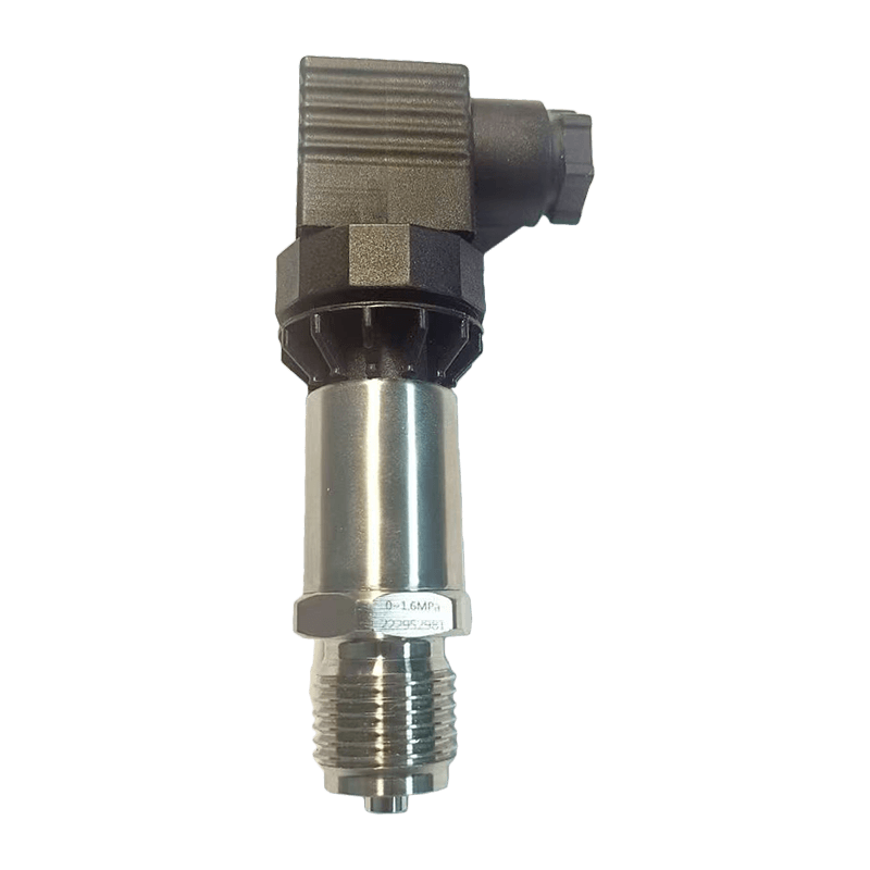
Elevator doors are among the most frequently operated and safety-critical components in a lift installation. Every journey depends on the doors opening smoothly, closing accurately, responding quickly to commands, and stopping reliably when an obstruction is detected. Although the door mechanism may appear simple from the outside, its performance depends on the coordinated operation of the motor, encoder, control algorithm, sensors, safety circuits, communication interfaces, and mechanical transmission system.
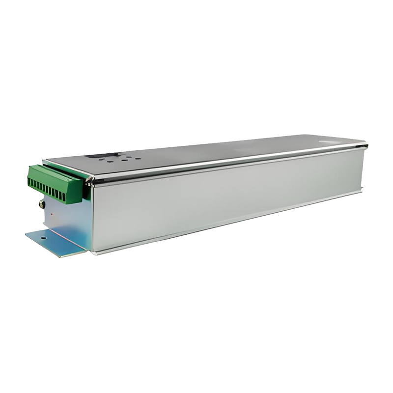
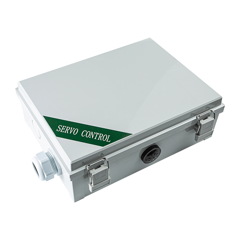
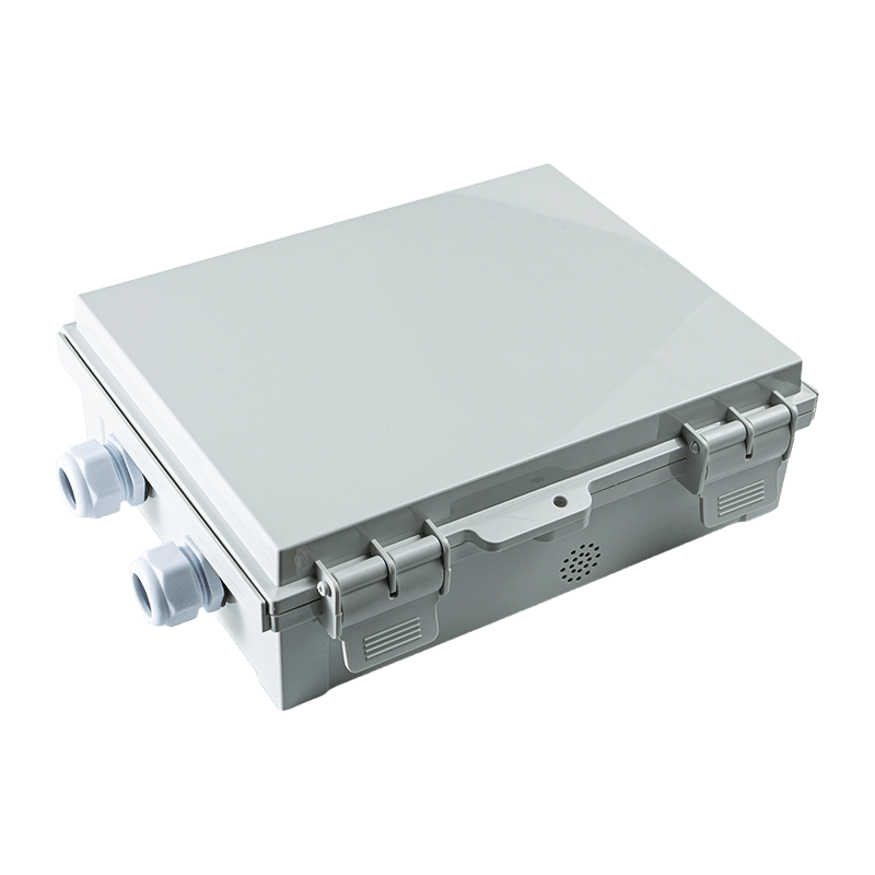
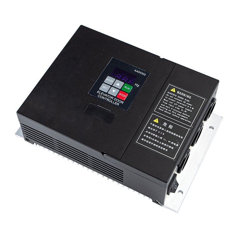
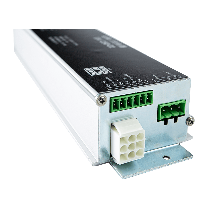
The Elevator Door Controller AIG-500E-01 is designed to provide coordinated, accurate, and intelligent control for sliding elevator door systems. It combines fully closed-loop space vector PWM control with extensive parameter adjustment, integrated monitoring, flexible input and output functions, and compatibility with permanent magnet servo motor systems. The result is a compact controller capable of supporting smooth door movement, accurate positioning, convenient commissioning, and reliable operation in demanding elevator applications.
Developed for export elevator doors, villa elevator doors, and specially customized door operator systems, the controller is suitable for manufacturers, elevator integrators, service companies, and modernization projects. Its design addresses many of the challenges that affect conventional door controllers, including difficult commissioning, inconsistent door curves, poor visibility of operating data, limited compatibility, and insufficient fault feedback.
This article examines the architecture, operating advantages, application value, manufacturing strengths, and integration possibilities of the Elevator Door Controller. It also explains how a controller of this type can improve elevator door performance while supporting efficient production, system customization, and long-term serviceability.
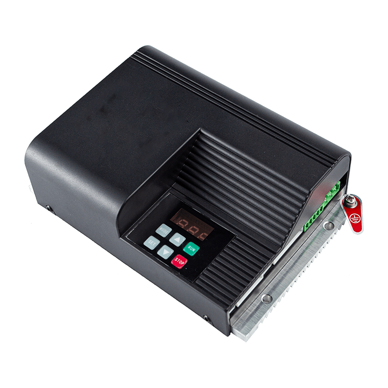
Elevator Door Controller
1. The Role of a Dedicated Elevator Door Controller
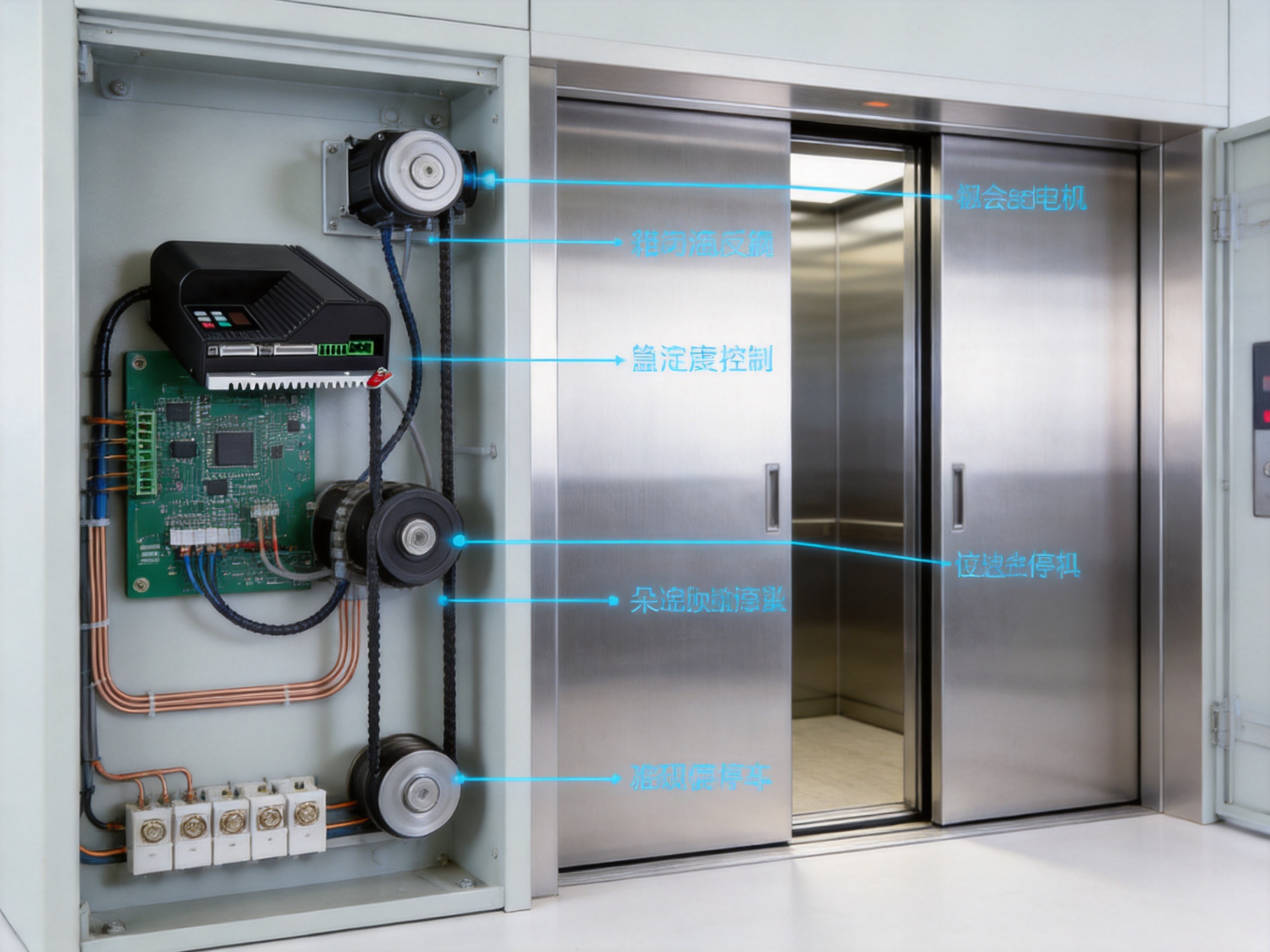
An elevator door controller is the electronic coordination center of the door operator. It receives commands from the elevator control system, processes signals from safety devices and position sensors, drives the motor, monitors operating conditions, and communicates the door status to other equipment. The controller must manage these functions without compromising passenger safety or mechanical reliability.
During a normal opening cycle, the controller receives an open command, accelerates the motor smoothly, controls the door speed through multiple stages, reduces speed before the end of travel, and stops the door at the correct open position. During closing, it performs the same process in reverse while also monitoring anti-pinch devices, fire-protection signals, arrival signals, and other safety-related inputs.
Unlike a simple motor relay or basic variable-speed drive, a dedicated door controller is designed around the unique requirements of elevator door movement. Door travel is short but frequent. Acceleration and deceleration must be comfortable for passengers. The door must maintain appropriate force and speed throughout the cycle. It must also react quickly if a safety edge, light curtain, or other protective device identifies an obstruction.
The AIG-500E-01 addresses these requirements with a combination of closed-loop control, configurable door curves, digital monitoring, and dedicated elevator I/O. Its architecture is intended to make the door operator easier to commission and more consistent in daily operation.
2. Product Architecture and Core Operating Principle
2.1 Fully Closed-Loop Space Vector PWM Control
The controller uses fully closed-loop space vector pulse-width modulation control. This control method enables accurate regulation of motor torque and speed by continuously evaluating feedback from the motor system. Instead of operating the motor through a limited number of fixed states, the controller can adjust the voltage and frequency supplied to the motor in a more refined manner.
Closed-loop control is especially valuable in elevator door applications because the door load can vary. Friction, belt tension, guide rail conditions, door panel weight, temperature, and installation alignment can all influence the required motor torque. A controller that operates without feedback may deliver acceptable results under one set of conditions but become unstable or inconsistent when the mechanical environment changes.
By using feedback, the AIG-500E-01 can maintain greater control over speed, position, and stopping behavior. This helps reduce abrupt movement, improve repeatability, and support more accurate positioning at the open and closed limits. It also provides a foundation for monitoring abnormal operating conditions and adjusting the door profile during commissioning.
2.2 Motor Compatibility
The controller is specifically designed to work with the MT01-TB-120W permanent magnet servo motor. It also supports a controllable 24 V DC brushless motor or servo motor, with a maximum output current of 7.5 A and maximum output power of 150 W. This gives system designers flexibility when selecting a compatible motor and adapting the controller to different door operator configurations.
Permanent magnet servo motors are well suited to elevator door systems because they can provide efficient torque production, compact construction, and responsive speed control. When combined with an encoder and a closed-loop drive, they allow the controller to manage movement with greater precision than a conventional open-loop motor arrangement.
The compatibility with a defined motor platform also benefits integrators. A controller and motor that have been designed to operate together can reduce uncertainty during installation and commissioning. At the same time, the controller’s broader support for compatible brushless and servo motor arrangements can be useful for customized or replacement projects.
2.3 Single-Phase Input and Integrated Power Supply
The AIG-500E-01 operates from a single-phase input of 176–264 VAC at 50 or 60 Hz. This input range supports common electrical supply conditions in many markets and provides a practical solution for elevator door operator cabinets and control enclosures.
The controller also includes an integrated 24 V switching power supply. An integrated supply can simplify system design by reducing the need for separate power modules, additional wiring, and external mounting space. It can also make installation more organized, particularly where the door controller is installed in a compact enclosure.
Combining the motor-control electronics, auxiliary power supply, I/O circuitry, and communication functions in one product helps reduce the number of separate components within the door operator system. Fewer external modules can simplify troubleshooting and provide a clearer relationship between the door control logic and the connected field devices.
3. Intelligent Door Motion Management
3.1 Multi-Stage Speed Profiles
One of the most important advantages of the controller is its extensive door curve adjustment capability. Opening and closing curves can be configured through the O and C parameter groups. These settings allow technicians to adjust multiple speed gears, buffer distances, acceleration values, and deceleration values.
Elevator doors rarely benefit from a single constant speed. A typical opening cycle may require a controlled acceleration phase, a faster travel phase, a gradual reduction in speed, and a soft final stop. Closing may use a different profile because of passenger protection requirements, mechanical resistance, and the need to maintain suitable closing force.
With multiple adjustable speed stages, the controller can be adapted to different door widths, panel weights, mechanical transmission ratios, and installation conditions. A narrow villa elevator door may require a different curve from a wide commercial elevator door. A customized door operator may also require a different acceleration and buffer strategy from a standard export door system.
Fine adjustment of the door curve can provide several benefits:
Improved passenger comfort through smoother acceleration and deceleration.
Reduced mechanical impact at the end of travel.
Lower stress on belts, pulleys, bearings, and door panels.
More consistent opening and closing times.
Better adaptation to different door widths and mechanical loads.
Reduced risk of door rebound or incomplete positioning.
The ability to adjust these characteristics in software is more efficient than relying only on mechanical changes. It allows technicians to optimize the door while preserving the basic structure of the operator.
3.2 Accurate End Position Control
Door positioning is a fundamental part of elevator reliability. If the door stops too early, it may not provide a full clear opening. If it overshoots the intended position, it can create mechanical impact or cause the door to move against a stop. The AIG-500E-01 supports accurate door position management through closed-loop motor control and configurable position-related parameters.
The controller monitors the movement of the door and uses feedback to determine how the door is progressing through its travel. This allows the system to reduce speed at an appropriate point and complete the movement with a controlled stop. Accurate positioning also supports the relay outputs for open-position reached and close-position reached signals.
Reliable position feedback is important not only for passenger access but also for communication with the main elevator controller. The elevator system must know whether the door is fully open, fully closed, moving, blocked, or in a fault state. Clear position information helps coordinate elevator dispatching and prevents unsafe or inefficient operating sequences.
3.3 Automatic One-Key Commissioning
Commissioning is often one of the most time-consuming stages of elevator door installation. The technician must identify the door travel range, determine the initial position, confirm motor operation, check the direction of movement, and optimize acceleration and deceleration. If these tasks require extensive manual calculation, installation time increases and the possibility of configuration errors becomes greater.
The AIG-500E-01 includes an automated one-key debugging function identified as A-c. This function can measure door width and test the initial position. By automating these basic setup tasks, the controller helps reduce the time required to establish an operating profile.
One-key commissioning does not eliminate the need for professional installation or safety verification. Instead, it provides a structured starting point for technicians. After the automatic process, the door curve can be reviewed and adjusted according to the installation conditions. This combination of automatic measurement and manual optimization is more practical than either approach alone.
For elevator manufacturers and service companies, faster commissioning can improve project efficiency. For modernization projects, it can reduce the time that a lift remains unavailable. For customized systems, the automatic setup function can help technicians establish a repeatable baseline before applying application-specific parameters.
4. Monitoring and Diagnostic Visibility
A controller is more useful when technicians can clearly observe what is happening inside the system. The AIG-500E-01 includes a digital display that tracks output speed, current, busbar voltage, door position, and total run time. These values provide immediate insight during commissioning, maintenance, and fault analysis.
4.1 Output Speed
Output speed information helps technicians verify whether the motor is following the intended door curve. If the actual speed is lower than expected, the cause may involve excessive friction, mechanical obstruction, incorrect settings, or insufficient motor performance. If the speed is unstable, the issue may involve feedback, tuning, wiring, or mechanical alignment.
4.2 Motor Current
Current monitoring provides an indication of motor load. An increase in current may suggest friction, a misaligned door, an obstruction, excessive belt tension, or a mechanical component nearing the end of its service life. Monitoring current during commissioning also helps technicians identify whether the selected profile is appropriate for the mechanical system.
4.3 Busbar Voltage
Busbar voltage monitoring helps assess the internal electrical operating condition of the controller. Abnormal voltage may be associated with input supply issues, power fluctuations, or other electrical conditions. Having this value available from the controller display can make troubleshooting more direct.
4.4 Door Position
Door position information allows the technician to verify travel range and stopping behavior. It is particularly useful when adjusting buffer distances and confirming the relationship between the encoder feedback and the physical door movement.
4.5 Total Run Time
Total run time can support preventive maintenance planning and service records. A door operator that has completed a high number of operating hours may require closer inspection of belts, rollers, guide components, bearings, and other mechanical parts. Run-time information can also help compare service conditions across different installations.
Compared with controllers that provide little or no internal operating information, a digital display can significantly reduce diagnostic effort. Technicians can obtain useful data at the equipment rather than depending entirely on external meters or trial-and-error adjustments.
5. Safety-Oriented Input and Output Functions
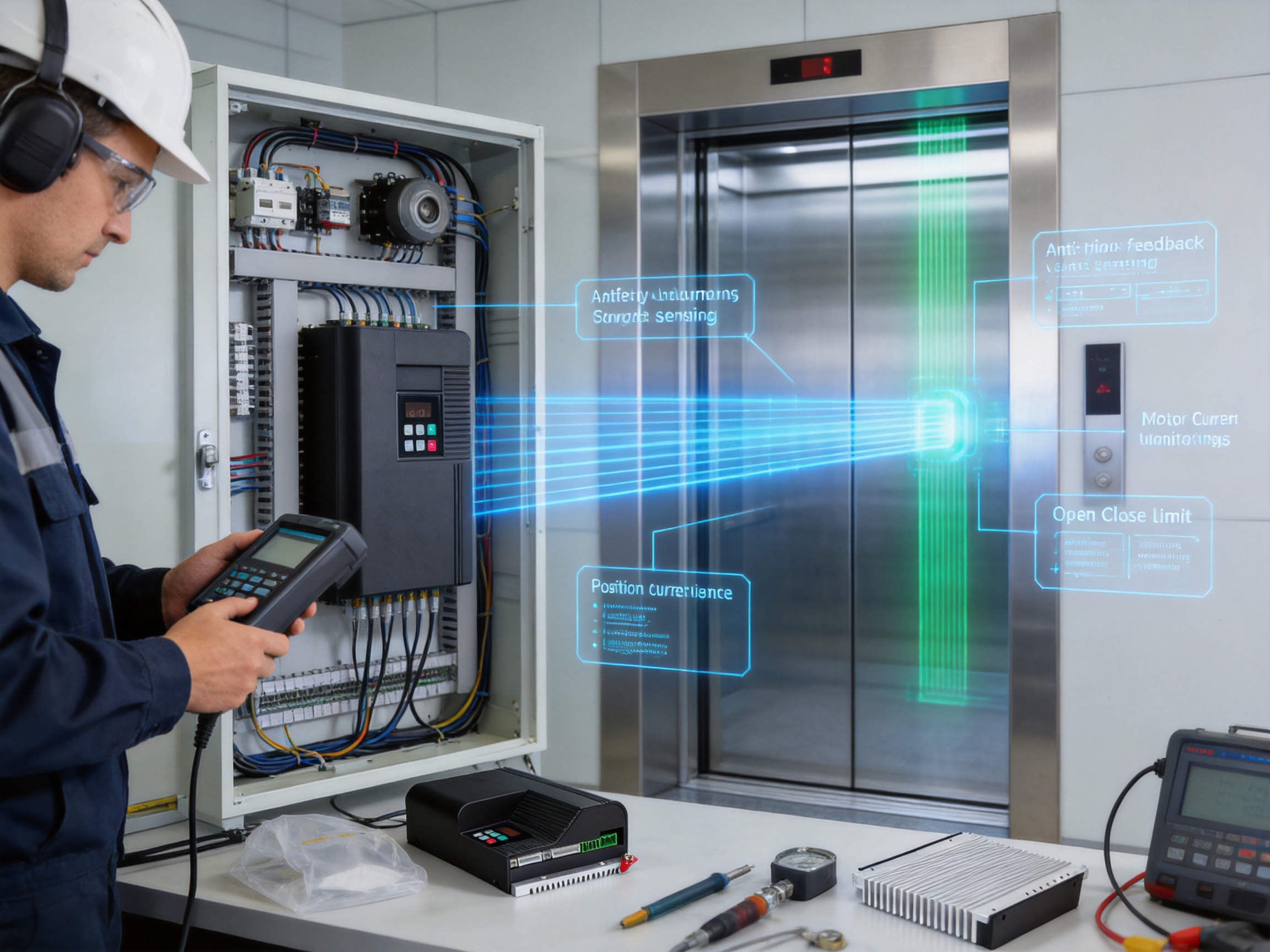
Elevator door control must respond to a wide range of external signals. The AIG-500E-01 provides eight digital inputs for commands, safety signals, and protective functions. These inputs can be configured for signals such as open, close, anti-pinch, fire protection, arrival, and motor thermal protection.
5.1 Open and Close Commands
The open and close command inputs connect the door operator with the main elevator control system. The controller supports both level and edge switching gate signal modes. This flexibility allows the device to work with different signal strategies used by elevator control architectures.
Level-based control maintains an active signal while a command is present. Edge-based control responds to a transition in the signal. Supporting both methods can simplify integration when replacing an existing door controller or connecting to a customized elevator control cabinet.
5.2 Anti-Pinch and Fire Protection Signals
Anti-pinch and fire-protection signals are essential to safe elevator operation. When a protective device identifies an obstruction or a special operating condition is activated, the door controller must respond according to the configured control logic. The dedicated input structure allows these signals to be connected directly to the door control system.
The exact safety behavior must always be coordinated with the applicable elevator safety architecture, local regulations, and the requirements of the complete lift system. The controller is a component within that safety system and must be installed, configured, and tested by qualified personnel.
5.3 Arrival and Thermal Protection Signals
Arrival signals can help coordinate the door operation with the elevator’s position and dispatch logic. Motor thermal protection signals provide an additional method for monitoring motor temperature-related conditions. These inputs help the controller respond to the operational status of connected equipment rather than operating without regard to external conditions.
5.4 Relay Outputs
The controller provides three relay outputs for open position reached, close position reached, and fault alarm signals. These outputs can be connected to the elevator control system, indicator circuits, or other monitoring equipment.
Open and close position signals provide clear confirmation of the door state. The fault alarm output can notify the main controller or maintenance personnel when the door operator detects an abnormal condition. This separation between control inputs and status outputs gives system integrators a practical interface for building a complete door operating sequence.
6. Communication and Parameter Management
Modern elevator systems increasingly require communication capabilities for setup, service, data exchange, and integration with other controllers. The AIG-500E-01 is equipped with RS-485 communication networking and supports TTL communication for data copying and external parameter setting or debugging.
6.1 RS-485 Networking
RS-485 is widely used in industrial control because it supports robust serial communication over practical cable distances and can connect multiple devices within an organized network. In an elevator door application, the interface can support communication between the door controller, a service tool, or a higher-level control system, depending on the system configuration.
The use of an industrial communication interface provides more flexibility than a controller based only on discrete wiring. It can support access to parameters, operating data, and service functions while preserving the dedicated input and output connections required for safety and command signals.
6.2 TTL Communication for Data Copying
TTL communication supports data copying and external parameter setting or debugging. This can be valuable when multiple door controllers use similar configurations. A technician or manufacturer may prepare a standard parameter set and transfer it to another controller, reducing repetitive manual entry.
Parameter copying can also improve consistency during production. When a door operator design has been validated, the approved settings can be reproduced across a series of units. Technicians can then apply only the adjustments required by the specific door width, motor arrangement, or installation environment.
6.3 Parameter Groups
The controller’s parameter structure includes door curve groups and technician configuration groups. The O and C groups manage opening and closing characteristics, while the F group includes settings such as motor pole pairs, encoder lines, and relay output functions.
This separation supports a logical workflow. Door movement can be adjusted without unnecessarily changing motor identification parameters, while technician-level settings can be protected through controlled commissioning procedures. A clearly organized parameter system also helps maintenance personnel understand which values affect motion and which values affect system configuration.
7. Advantages Compared with Conventional Door Controllers
7.1 More Precise Motion Control
Many basic door controllers rely on limited speed steps or open-loop control. These methods may be adequate for simple applications but can produce inconsistent movement when door loads vary. The AIG-500E-01 uses closed-loop space vector PWM control, allowing more precise regulation of motor behavior.
The practical advantage is not simply a more advanced technical specification. It is the ability to create a door movement profile that is smoother, more repeatable, and better matched to the actual mechanical system. This can improve the passenger experience and reduce unnecessary mechanical stress.
7.2 Faster Setup
Conventional controllers may require technicians to manually estimate door width, determine travel limits, and enter multiple setup values before the door can operate correctly. The one-key debugging function provides an automated measurement and initial-position test, helping reduce the initial setup workload.
7.3 Greater Parameter Flexibility
A limited controller may offer only a few fixed settings. By contrast, the AIG-500E-01 provides adjustable opening and closing curves, multiple speed gears, buffer distances, acceleration, deceleration, motor parameters, encoder settings, and relay functions. This makes it better suited to a broader range of door mechanisms and customized systems.
7.4 Better On-Site Visibility
Digital monitoring of speed, current, busbar voltage, position, and total run time gives technicians more information than a controller with only basic indicator lights. Improved visibility can shorten troubleshooting and help service personnel make adjustments based on operating data rather than assumptions.
7.5 Flexible Integration
The combination of eight digital inputs, three relay outputs, RS-485, and TTL communication provides multiple integration options. The controller can be connected to command signals, safety devices, position confirmation circuits, fault monitoring systems, and external configuration tools.
7.6 Compact System Design
The integrated 24 V switching power supply helps reduce the number of external components required in the door operator system. A more integrated design can simplify cabinet layout, reduce wiring complexity, and make replacement or service work more manageable.
7.7 Application Versatility
The controller is intended for export elevator doors, villa elevator doors, and specially customized door operator systems. This range demonstrates that the design is not limited to one narrow installation type. Its configurable motion profiles and communication functions allow it to support different market requirements and project conditions.
| Feature | Elevator Door Controller AIG-500E-01 | Typical Basic Controller Limitation | Application Benefit |
|---|---|---|---|
| Control method | Fully closed-loop space vector PWM | Limited-step or open-loop control | Improved speed, torque, and position regulation |
| Commissioning | One-key door-width measurement and initial-position test | More manual setup and adjustment | Reduced commissioning time |
| Door profiles | Multiple opening and closing speed gears with adjustable acceleration, deceleration, and buffers | Few fixed speed settings | Better adaptation to door size and mechanical load |
| Monitoring | Speed, current, busbar voltage, position, and total run time | Limited status indication | Faster diagnosis and preventive maintenance |
| Inputs | Eight digital inputs | Restricted I/O capacity | Flexible connection of commands and safety signals |
| Outputs | Three relay outputs for position and fault status | Minimal status feedback | Clearer interface with the elevator control system |
| Communication | RS-485 networking and TTL data copying or debugging | Discrete wiring only | Improved parameter management and integration |
| Power architecture | Integrated 24 V switching power supply | Separate auxiliary supply often required | Simplified system design |
8. Manufacturing and Engineering Strengths
The performance of an industrial controller depends not only on its circuit design but also on the quality of its manufacturing process. A controller used in elevator applications must be produced with attention to electrical consistency, mechanical durability, software reliability, and traceable testing. ASY Electronics is positioned as a high-tech enterprise focused on data sensing, intelligent connectivity, and industrial equipment solutions.
8.1 Experience in Industrial Electronics
The company’s product portfolio includes broadband power line carriers, wireless temperature monitoring systems, industrial transmitters, thermal gas mass flow meters, and automatic door controllers. This combination reflects experience across sensing, communications, measurement, and control technologies.
Such cross-disciplinary capability is valuable for elevator door controller development. A modern door operator is not only a motor drive. It is also a sensing device, a communication node, a safety interface, and an embedded industrial control product. Knowledge gained from other industrial electronics products can contribute to a more integrated approach to hardware, firmware, signal processing, and system connectivity.
8.2 Design for Integrated Industrial Solutions
The company’s stated mission is to support efficient, reliable, and green smart factories through self-developed edge-layer hardware and industrial data integration solutions. This orientation encourages product development that considers the complete operating environment rather than focusing on a single circuit function.
For the Elevator Door Controller, this systems-oriented approach can be seen in the combination of motion control, monitoring, configurable parameters, I/O, networking, and external debugging. These functions allow the controller to serve as an edge device within the elevator door system, collecting operating information while controlling the physical mechanism.
8.3 Manufacturing Process Considerations
Advanced manufacturing for an industrial controller should cover the full product lifecycle, beginning with design verification and continuing through component sourcing, printed circuit board assembly, firmware loading, functional testing, parameter verification, enclosure assembly, and final inspection.
For a product such as the AIG-500E-01, manufacturing quality is particularly important in the following areas:
Printed circuit board assembly must maintain reliable solder joints and accurate component placement.
Power conversion circuits must be checked for insulation, voltage stability, and thermal behavior.
Motor output circuits must be verified under appropriate current and load conditions.
Digital input and relay output channels must be tested for correct switching behavior.
Encoder and communication interfaces must be checked for signal integrity and correct data exchange.
Firmware and parameter functions must be validated against the intended control logic.
Display and user-interface functions must be confirmed before shipment.
Mechanical assembly must protect the electronics from vibration, contamination, and installation stress.
Although detailed factory equipment and process statistics are not specified in the available product materials, the product’s industrial positioning and broad control functionality indicate the importance of structured production and verification. Manufacturers and buyers should evaluate traceability, inspection records, calibration practices, firmware control, and final functional testing when selecting a supplier.
8.4 Quality Consistency Through Standardized Parameters
The controller’s TTL data-copying capability can support more consistent manufacturing and commissioning. Once a validated parameter set has been established for a particular door operator design, the same configuration can be transferred to multiple units. This helps reduce variation caused by manual entry and supports more repeatable production results.
Standardized parameters do not mean that every installation is identical. Instead, they provide a controlled baseline. Individual units can then be adjusted for door width, mechanical tolerance, motor characteristics, and site conditions. This combination of standardization and flexibility is useful for both mass production and customized projects.
8.5 Product Development for Custom Applications
Elevator door systems vary by region, building type, door size, motor selection, signaling method, and safety architecture. A controller that cannot be adapted may force the integrator to redesign the entire system. The AIG-500E-01’s programmable parameters and flexible interfaces are better suited to customized applications.
The company’s broader industrial product experience also supports the development of application-specific solutions. Customers may require adjustments to communication, parameter management, I/O assignment, or integration procedures. A supplier familiar with industrial customization can provide more practical support than a vendor focused only on standardized consumer products.
9. Applications Across Different Elevator Environments
9.1 Export Elevator Doors
Export projects often involve different voltage standards, communication practices, installation methods, and service expectations. The 176–264 VAC single-phase input range supports common supply conditions, while the configurable control functions allow integrators to adapt the door profile to local project requirements.
RS-485 communication and external parameter setting can also help service teams manage equipment across different installations. Clear digital monitoring is especially useful when remote technical support is limited and on-site personnel need direct access to operating values.
9.2 Villa Elevator Doors
Villa elevators often require quiet, smooth, and visually refined operation. Although the door loads may be lower than those of a large commercial elevator, passenger expectations can be high. A smooth multi-stage speed profile helps reduce noise and abrupt movement, while accurate positioning supports a neat and reliable door presentation.
The compact integrated design can also be useful where equipment space is limited. The controller can provide motor control, auxiliary power, monitoring, and signal interfaces without requiring a large collection of separate modules.
9.3 Customized Door Operator Systems
Specially customized door operators may use unusual door dimensions, different mechanical transmission systems, alternative motors, or nonstandard control interfaces. The adjustable O and C groups, F-group motor parameters, digital I/O, relay outputs, and communication functions provide a foundation for adapting the controller to these requirements.
Customized applications should be validated through appropriate mechanical and electrical testing. The controller’s flexibility is an advantage, but the final system must still be assessed as a complete assembly, including the door panels, rollers, belts, motor, encoder, safety devices, and elevator control cabinet.
9.4 Demonstration and Test Applications
The controller includes a demo mode identified as F1.4 for continuous test cycling of the door mechanism. This mode can support product demonstrations, endurance testing, training, and service evaluation. Repeated cycling allows technicians to observe door consistency and identify mechanical issues that may not appear during a single operating cycle.
Continuous testing must be performed with appropriate safeguards. The test area should be controlled, and the equipment should be operated by qualified personnel who understand the risks associated with repeated mechanical movement.
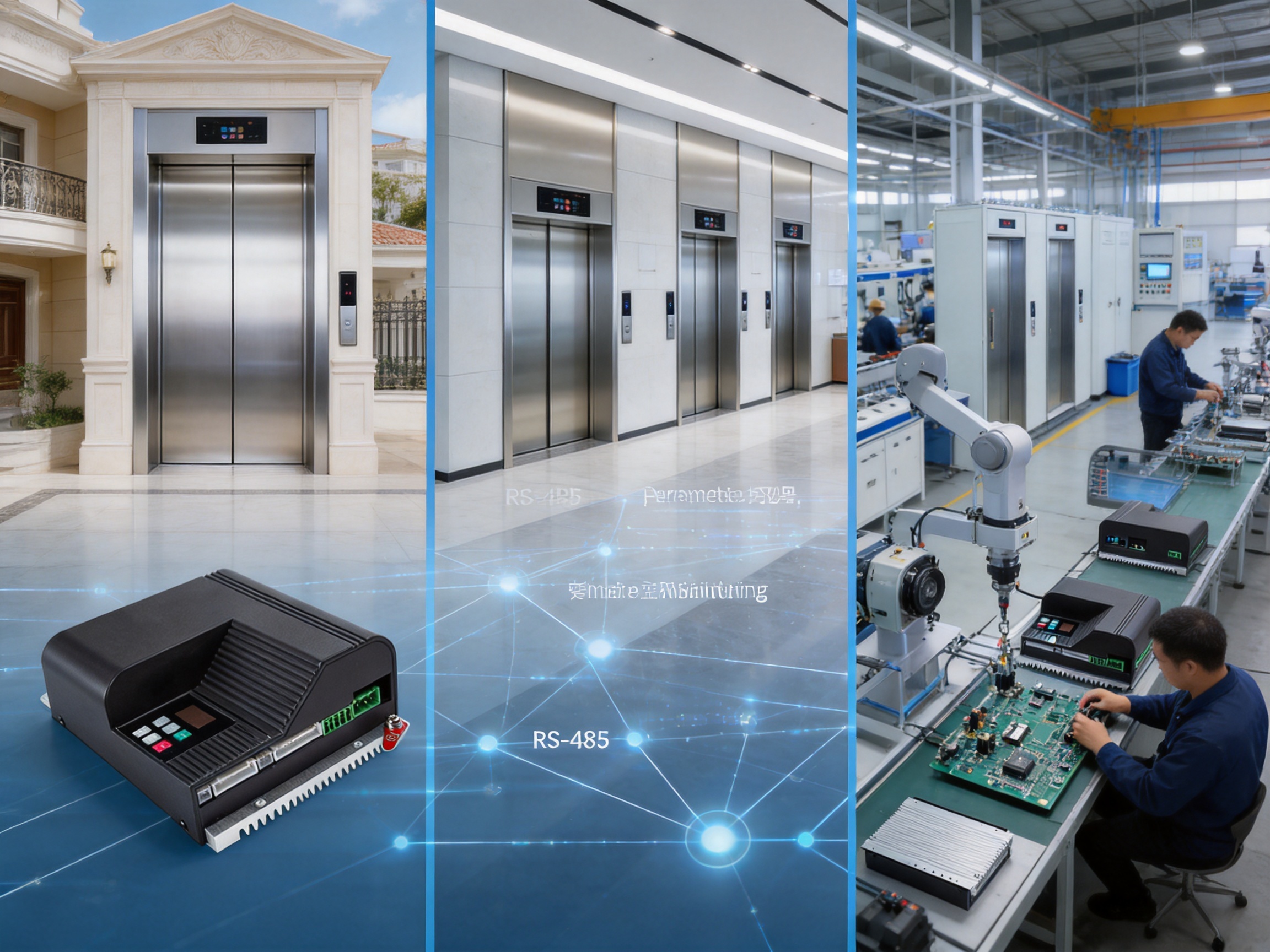
10. Installation and Commissioning Considerations
Successful operation depends on correct installation of both the controller and the mechanical door operator. Before applying power, the installer should verify the input voltage, grounding, motor compatibility, encoder wiring, input signal connections, relay output wiring, and communication connections.
The motor and encoder must be connected according to the approved wiring configuration. Incorrect encoder lines or motor pole-pair settings can lead to poor control or unexpected movement. These values are managed through technician parameters in the F group and should be confirmed before commissioning.
The door mechanism should move freely by hand when appropriate and safe to do so. Excessive friction, misaligned guide rails, damaged rollers, incorrect belt tension, or mechanical interference can cause high current, unstable motion, or repeated faults. Electronic adjustment cannot fully compensate for a poorly aligned mechanical system.
After wiring and mechanical inspection, the one-key debugging function can be used to measure the door width and test the initial position. The technician should then verify the direction of movement, open and close limits, safety inputs, relay outputs, and fault response.
Door curves should be adjusted gradually. Acceleration and deceleration values that are too aggressive may increase mechanical impact, while values that are too conservative may result in unnecessarily long travel times. Buffer distances should be selected to create a smooth approach to the final position without reducing the usable opening or closing range.
The technician should observe output speed, motor current, busbar voltage, and door position on the digital display during testing. These values can help identify whether the motion profile is suitable. The total run time can also be recorded as part of the commissioning documentation.
Safety devices must be tested independently and as part of the complete elevator control sequence. Anti-pinch, fire-protection, arrival, and thermal protection signals should be checked for correct logic and response. Relay outputs should also be verified at the main elevator controller or monitoring interface.
11. Maintenance and Lifecycle Value
A reliable door controller contributes to the lifecycle value of an elevator by helping the door system operate consistently over many cycles. However, electronic control cannot replace mechanical maintenance. The best results are achieved when the controller’s diagnostic information is combined with routine inspection of the complete door operator.
Maintenance personnel should monitor changes in motor current, speed stability, stopping position, operating noise, and total run time. A gradual increase in current may indicate mechanical wear or contamination. Changes in stopping position may suggest encoder issues, belt slippage, guide rail problems, or parameter changes. Irregular acceleration may indicate a control or mechanical problem requiring further investigation.
Because the controller includes digital monitoring, service teams can establish reference values during commissioning and compare them with later measurements. This supports condition-based maintenance rather than relying only on fixed service intervals.
Parameter management is also important over the lifecycle of the product. Approved settings should be documented and protected from unauthorized changes. If a controller is replaced, the TTL data-copying function may help transfer the relevant configuration, followed by a complete functional and safety check.
For elevator modernization, the controller can provide a practical way to improve door motion without replacing every part of the lift system. The feasibility of any retrofit depends on motor compatibility, mechanical dimensions, encoder type, electrical architecture, applicable regulations, and the condition of the existing door operator.
12. Energy, Reliability, and Passenger Experience
Efficient motor control can support lower energy consumption by matching motor output more closely to the required movement profile. Permanent magnet servo motors are generally associated with efficient torque production, and closed-loop control can reduce unnecessary overcorrection during operation.
Energy performance depends on many factors, including door mass, cycle frequency, motor efficiency, mechanical friction, acceleration settings, and standby behavior. Nevertheless, a well-tuned controller can help avoid inefficient motion caused by excessive acceleration, repeated correction, or prolonged operation against mechanical resistance.
Reliability is also connected to passenger experience. Passengers may not notice the controller directly, but they notice doors that slam, hesitate, reopen unexpectedly, close unevenly, or stop inaccurately. A smoother and more predictable door cycle contributes to the perceived quality of the entire elevator.
In commercial buildings, reliable door operation can also improve traffic flow. Faster recovery after a door command, consistent opening time, and accurate close confirmation help the elevator system dispatch cars more effectively. In residential applications, reduced noise and gentle movement may be particularly important.
13. Why an Industrial Supplier Matters
Selecting a door controller is not only a decision about electronic specifications. It is also a decision about technical support, customization capability, production consistency, communication, and long-term cooperation. An industrial supplier with experience in sensing and intelligent connectivity can offer a broader understanding of how equipment operates within a complete system.
ASY Electronics develops products for smart factory applications, equipment condition monitoring, energy management, and production process optimization. This background is relevant because the Elevator Door Controller also combines physical control with operating data and communication functions.
A supplier with a wider industrial portfolio may be better positioned to understand requirements such as data access, remote service, parameter standardization, signal integration, and customized interfaces. These requirements are becoming increasingly important as elevator equipment becomes more connected and service organizations seek better visibility into field performance.
Manufacturing strength is equally important. A controller may include advanced functions, but those functions must be delivered consistently from one production batch to another. Controlled assembly, firmware verification, electrical testing, and final inspection are essential to ensuring that the product performs as expected after installation.
Customers evaluating the controller should consider the supplier’s ability to provide documentation, wiring guidance, parameter support, application consultation, replacement assistance, and technical response. These factors can have a significant influence on total project cost and operational reliability.
14. Recommended Selection Criteria for Buyers
Before selecting an elevator door controller, buyers should compare more than rated voltage and motor power. The following factors are important for determining whether a controller will meet the requirements of a specific project.
First, verify the motor type and encoder arrangement. The controller must be compatible with the selected permanent magnet servo motor or brushless motor, and the relevant pole-pair and encoder-line parameters must be supported.
Second, review the input and output requirements. The system should have enough inputs for open, close, anti-pinch, fire-protection, arrival, and thermal signals. Relay outputs should support the required open, close, and fault status feedback.
Third, evaluate commissioning functions. Automatic door-width measurement and initial-position testing can reduce setup time, but technicians should also have access to detailed manual parameters for final optimization.
Fourth, examine the available diagnostic information. Speed, current, busbar voltage, position, and run-time monitoring can help reduce maintenance costs and improve fault analysis.
Fifth, assess communication requirements. RS-485 networking and TTL parameter copying may be valuable for production, integration, service, and future system upgrades.
Sixth, confirm the power architecture. The 176–264 VAC single-phase input and integrated 24 V switching power supply should be suitable for the intended installation and cabinet design.
Finally, review supplier capability. Product quality, technical documentation, application support, customization, and manufacturing consistency are all important when the controller will be used in multiple elevator projects.
15. Frequently Asked Questions
Q1: What type of equipment is the AIG-500E-01?
The AIG-500E-01 is a high-performance servo controller for sliding elevator and lift door systems. It manages motor speed, position, acceleration, deceleration, safety-related signals, status outputs, and communication functions.
Q2: What input voltage does the controller require?
The controller operates with a single-phase input of 176–264 VAC at 50 or 60 Hz.
Q3: Which motors can be used with the controller?
The controller is designed to work with the MT01-TB-120W permanent magnet servo motor. It also supports a controllable 24 V DC brushless motor or servo motor, with a maximum output current of 7.5 A and maximum output power of 150 W.
Q4: Does the controller include an auxiliary power supply?
Yes. The controller includes an integrated 24 V switching power supply, which can simplify the design and wiring of the door operator system.
Q5: How does one-key debugging work?
The one-key debugging function, identified as A-c, performs door-width measurement and an initial-position test. It provides a convenient starting point for commissioning, after which technicians can review and fine-tune the motion parameters.
Q6: Can opening and closing speeds be adjusted independently?
Yes. The O and C parameter groups provide separate adjustment of opening and closing door curves. Technicians can configure multiple speed gears, acceleration, deceleration, and buffer distances for each direction.
Q7: What information is shown on the digital display?
The display can show output speed, current, busbar voltage, door position, and total run time. These values assist with commissioning, troubleshooting, and preventive maintenance.
Q8: How many digital inputs are available?
The controller provides eight digital inputs. They can be used for signals such as open, close, anti-pinch, fire protection, arrival, and motor thermal protection, according to the system configuration.
Q9: What relay outputs are provided?
Three relay outputs are available for open position reached, close position reached, and fault alarm signals.
Q10: Does the controller support communication networking?
Yes. The controller includes RS-485 communication networking and TTL communication for data copying and external parameter setting or debugging.
Q11: Is there a test mode?
Yes. The controller includes a demo mode identified as F1.4 for continuous test cycling of the door mechanism. Test operation should be performed in a controlled environment by qualified personnel.
Q12: Can the controller be used for customized door operator systems?
Yes. Its adjustable motion profiles, technician parameters, flexible I/O, relay outputs, and communication functions make it suitable for specially customized door operator systems. Compatibility must be verified for each specific motor and mechanical design.
Q13: Can the controller replace an existing door controller?
It may be suitable for a replacement or modernization project, but compatibility must be evaluated carefully. The installer should verify the motor, encoder, mechanical operator, wiring, input logic, power supply, and safety architecture before replacement.
Q14: What maintenance information can be obtained from the controller?
Technicians can observe speed, current, busbar voltage, door position, and total run time. Changes in these values may help identify mechanical wear, electrical abnormalities, or parameter issues.
Q15: Who should install and commission the controller?
Installation, commissioning, and safety testing should be performed by qualified elevator professionals who understand motor control, elevator door mechanisms, electrical safety, and applicable regulations.
16. Conclusion
The Elevator Door Controller AIG-500E-01 provides a comprehensive control platform for modern sliding elevator doors. Its fully closed-loop space vector PWM control, compatibility with permanent magnet servo motors, multi-stage door curve adjustment, automatic one-key commissioning, digital monitoring, flexible I/O, relay outputs, and communication interfaces address the main technical requirements of reliable elevator door operation.
Compared with basic controllers that offer limited adjustment and little diagnostic information, this controller provides greater precision, better commissioning efficiency, stronger integration capability, and improved service visibility. Its integrated 24 V power supply further simplifies the system design.
The controller is suitable for export elevator doors, villa elevators, and customized door operator systems. Its configurable architecture allows integrators to adapt the motion profile and signal interface to different mechanical and control environments. The demo mode, parameter copying functions, and networking interfaces also support production testing, service, and long-term maintenance.
The product is backed by the industrial electronics capabilities of ASY Electronics, a company focused on intelligent connectivity, data sensing, equipment monitoring, energy management, and industrial data integration. This broader technology background supports the development of control products that are not only functional but also suitable for connected industrial applications.
When correctly matched with the motor, mechanical door operator, safety devices, and elevator control system, the AIG-500E-01 can help deliver smooth passenger movement, accurate door positioning, dependable status feedback, and efficient technical service. For elevator manufacturers and system integrators seeking a flexible and industrially oriented door control solution, it represents a practical platform for both standard and customized projects.
References
1. Product specification materials for the Elevator Door Controller AIG-500E-01.
2. Technical information concerning MT01-TB-120W permanent magnet servo motor compatibility.
3. General principles of closed-loop servo motor control and space vector pulse-width modulation.
4. Industrial practices for elevator door operator commissioning, safety signal integration, and preventive maintenance.
5. General guidance on RS-485 industrial communication and serial networking.
6. Industrial automation principles for equipment condition monitoring and intelligent edge-layer control.