

In modern industrial automation, gas flow is not merely a utility parameter; it is a direct factor affecting product consistency, energy efficiency, equipment safety, and process repeatability. From laboratory gas blending and semiconductor auxiliary processes to environmental test systems, analytical instruments, burner control, coating lines, and specialized manufacturing equipment, stable gas dosing and accurate gas measurement are essential. A proportional valve controlled thermal gas mass flow meter integrates flow sensing, digital processing, and closed-loop proportional valve control into one compact instrument, enabling users to measure and regulate clean gas flow with high accuracy, fast response, and dependable repeatability.
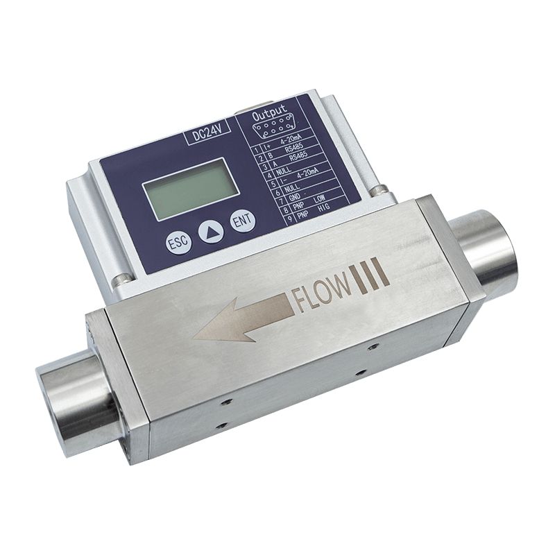
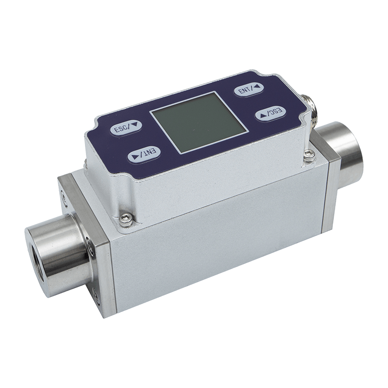
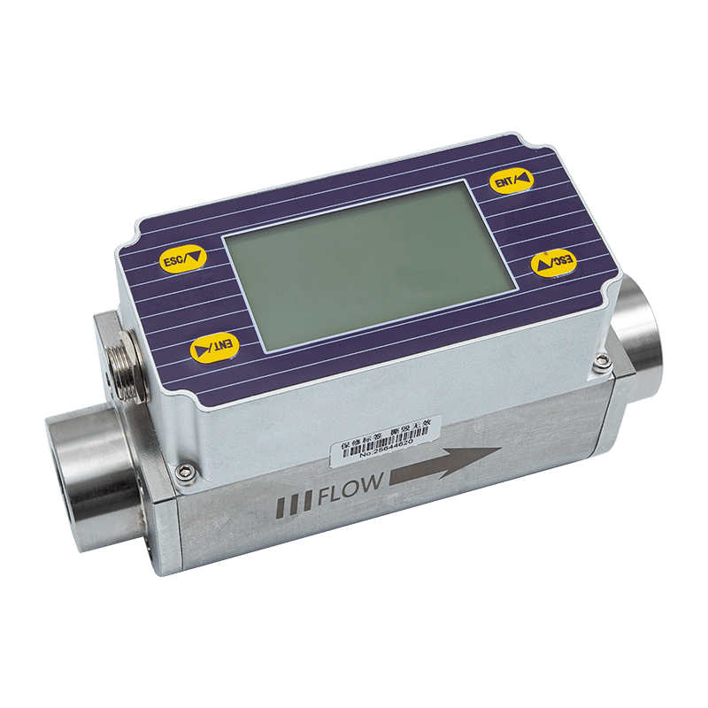
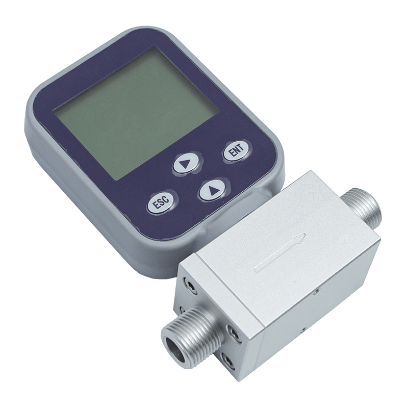
The AI-FC proportional valve controlled thermal gas mass flow meter is designed for applications that require both precise measurement and active flow control. It uses an advanced microelectromechanical system flow sensing chip, a bypass shunt structure, and an electromagnetic proportional valve to achieve stable mass flow measurement and controlled gas delivery. With control accuracy of plus or minus 1.0 percent of set point, measurement accuracy of 1 percent of full scale, a control and measurement range ratio of 1:100, RS485 communication with standard Modbus RTU protocol, an LCD interface, and standard analog input and output options, the product provides a practical and intelligent solution for industrial gas control systems.
Compared with conventional flow meters that only measure flow, this proportional valve controlled instrument can receive a target flow value and actively regulate the valve opening to maintain the desired gas flow. Compared with many simple mechanical rotameters or low-end electronic flow controllers, it delivers stronger stability, clearer digital integration, better anti-interference capability, faster response, and improved long-term usability. For equipment manufacturers and end users, this means fewer external components, simplified installation, easier system integration, and more reliable process outcomes.
Proportional Valve Control Type Thermal Gas Mass Flowmete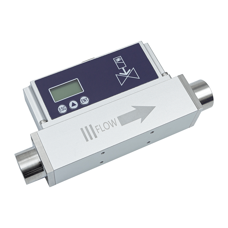
Product Overview and Application Value
The AI-FC product is a thermal gas mass flow meter with proportional valve flow control. It is built around a MEMS flow sensing chip and combines the advantages of thermal mass flow measurement with closed-loop control algorithms. The instrument measures the mass flow of gas directly, processes the signal digitally, compares the real-time flow with the required set point, and adjusts the electromagnetic proportional valve accordingly. This closed-loop architecture allows the device to maintain stable output even when upstream pressure, downstream resistance, or process conditions fluctuate within the specified operating range.
Thermal mass flow measurement is especially valuable in clean gas applications because it measures mass flow rather than only volumetric displacement. In many industrial processes, the actual number of gas molecules delivered is more important than volume under changing pressure or temperature conditions. By focusing on mass flow, the instrument helps users achieve better process repeatability, especially where gas dosing affects chemical reaction rates, flame characteristics, purge effectiveness, inerting performance, or analytical instrument stability.
The product supports a wide selection of flow specifications, including small flow ranges in SCCM and larger flow ranges in SLM. Its available ranges include 0 to 10, 20, 30, 50, 100, 200, 300, and 500 SCCM; 0 to 1, 2, 3, 5, 10, 20, and 30 SLM; 0 to 50 and 100 SLM; and 0 to 200 and 300 SLM. This broad selection allows it to serve both low-flow precision applications and medium-flow industrial gas control requirements.
The instrument can work with common gases such as air, nitrogen, oxygen, methane, argon, carbon dioxide, helium, hydrogen, and propane, subject to proper configuration and application assessment. Selectable standard temperature conditions include 0 degrees Celsius, 20 degrees Celsius, and 25 degrees Celsius, with 25 degrees Celsius as the default. This flexibility helps users align flow readings with their internal process standards and documentation systems.
Because the device includes an LCD, users can view instantaneous flow and cumulative flow directly on the instrument. The display also supports intuitive operation, allowing flow rates to be controlled through button input. For automated systems, control can be implemented through Modbus communication or analog input. This combination of local operation and remote integration makes the product suitable for pilot equipment, standalone machines, production lines, laboratory platforms, and industrial automation panels.
Core Technology: MEMS Sensor, Bypass Shunt, and Proportional Valve
The product’s performance is based on the coordinated operation of three core elements: the MEMS flow sensor chip, the bypass shunt, and the electromagnetic proportional valve. Each element contributes to measurement accuracy, stability, and control responsiveness.
The MEMS flow sensor chip is a miniature thermal sensing component manufactured using microelectromechanical system technology. MEMS technology enables highly sensitive flow detection in a compact structure. Because the sensing element is small and responsive, it can detect rapid flow changes and provide signals for fast digital processing. The product’s measurement response time is less than 50 milliseconds, allowing the control system to observe changes quickly and correct flow deviations efficiently.
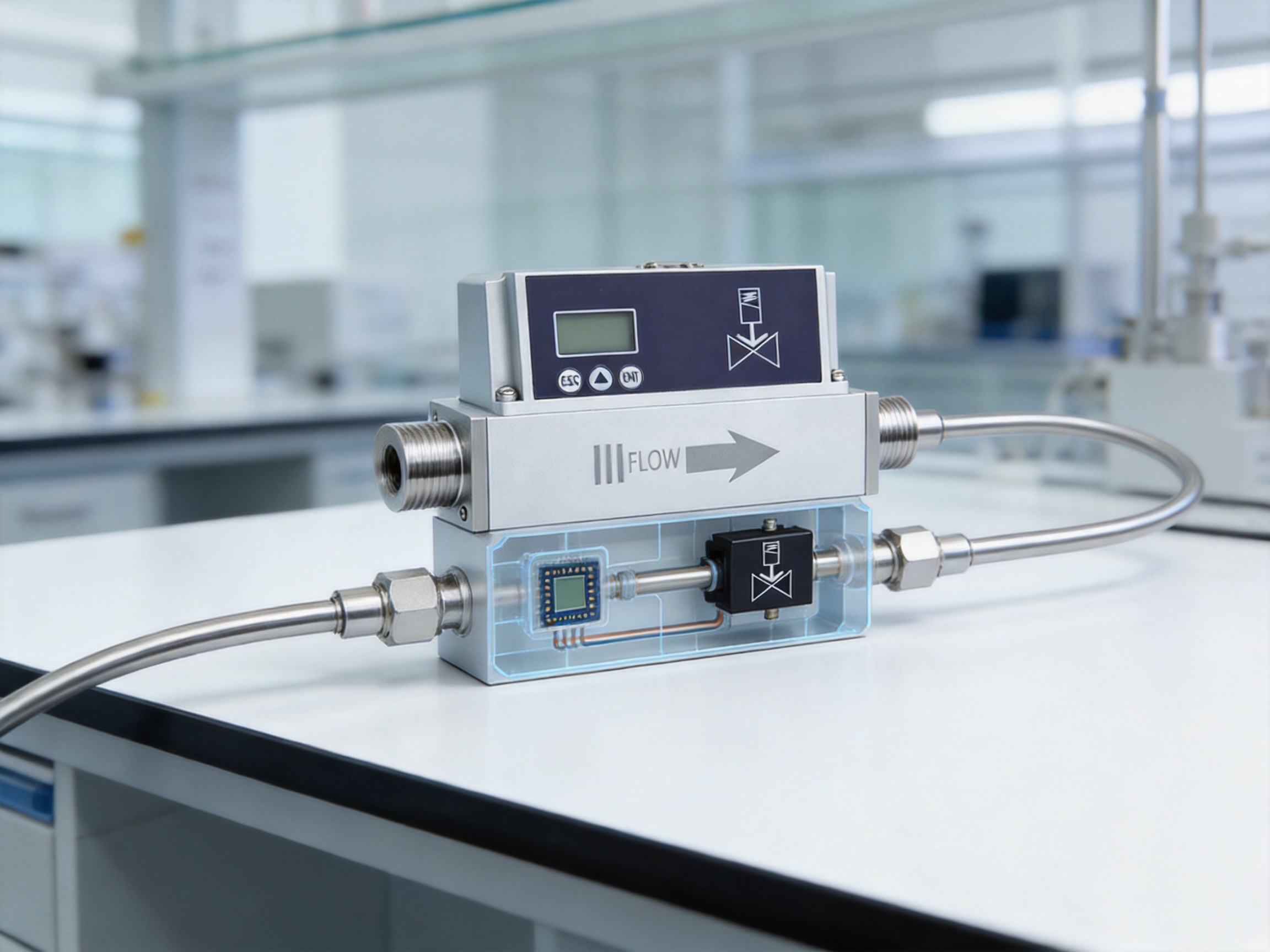
The bypass shunt structure is another important advantage. In a properly designed bypass thermal mass flow meter, only a controlled portion of the gas passes through the sensing channel, while the main flow passes through the shunt path. The distributor keeps the bypass fluid in a laminar flow state, which improves measurement stability and repeatability. Laminar flow behavior reduces turbulence-related noise and helps maintain a predictable relationship between the bypass sensing signal and the total flow. This is especially important for low-flow clean gas measurement, where small disturbances can create significant reading variation.
The electromagnetic proportional valve is used to regulate flow. Unlike a simple on-off solenoid valve, a proportional valve can modulate its opening according to the control signal. The valve used in the product is characterized by long service life and high sensitivity. The valve type is normally closed, which is beneficial for many safety-oriented gas systems because the valve tends toward a closed state when not actively driven. When combined with digital flow algorithms, the proportional valve allows the instrument to achieve controlled flow output with a typical control response time of less than 1.5 seconds to T90.
In a competitive environment, this integrated design provides a clear advantage over assemblies that combine a separate flow meter, controller, valve driver, and external proportional valve. Separate assemblies often require additional wiring, tuning, panel space, and integration time. They may also introduce mismatch between the sensor signal and valve control characteristics. By integrating sensing, valve control, display, analog output, and digital communication within one coordinated product, the AI-FC instrument reduces engineering complexity and improves consistency from unit to unit.
Key Technical Parameters
Parameter |
Specification |
Practical Meaning |
Working power supply |
DC 24 V, 12 W |
Suitable for common industrial control cabinets and automation systems. |
Control accuracy |
Plus or minus 1.0 percent of set point |
Maintains flow close to the requested value for stable process control. |
Measurement accuracy |
1 percent of full scale |
Provides reliable flow feedback across the selected measuring range. |
Control and measurement range ratio |
1:100 |
Enables useful control over a broad part of the rated range. |
Valve type |
Normally closed |
Supports safer gas handling behavior when the valve is not energized. |
Operating temperature |
Minus 10 to 55 degrees Celsius |
Suitable for many indoor industrial environments. |
Humidity |
Less than 95 percent relative humidity, no frost, no ice, no condensation |
Designed for normal industrial ambient conditions when condensation is avoided. |
Measurement response time |
Less than 50 milliseconds |
Detects flow changes quickly for responsive feedback. |
Typical control response time |
Less than 1.5 seconds to T90 |
Reaches the target flow quickly in automated control processes. |
Communication |
RS485, Modbus RTU protocol |
Easy integration with PLCs, controllers, gateways, and monitoring systems. |
Analog output and control |
Standard 4 to 20 mA; 1 to 5 V, 0 to 5 V, and 0 to 10 V customizable |
Compatible with both traditional and modern automation interfaces. |
Mechanical connection |
G1/4 and PT1/2 internal threads; other threads customizable |
Convenient for common industrial piping and equipment installation. |
Protection level |
IP40 |
Appropriate for protected equipment interiors and controlled environments. |
Measurement and Control Performance Advantages
One of the strongest advantages of the product is its combination of measurement and control accuracy. A control accuracy of plus or minus 1.0 percent of set point is valuable because process engineers typically need the actual flow to follow a set value, not simply to be displayed. In gas dosing processes, an accurate measurement without stable valve regulation may still result in poor process repeatability. Conversely, a valve controller without reliable mass flow feedback may drift with pressure changes. This instrument addresses both requirements in one closed-loop device.
The measurement accuracy of 1 percent of full scale supports dependable monitoring and quality control. When an operator or automation system reads the flow value, the reading can be used for production records, alarm logic, totalization, and process trend analysis. The LCD display shows instantaneous and cumulative flow rates, which is useful for both commissioning and daily operation. Instantaneous flow helps operators observe current process behavior, while cumulative flow helps track gas consumption, batch dosing, purge volume, or process totals.
The 1:100 control and measurement range ratio gives the product practical flexibility. In many factories, one process may require both high-flow operation and low-flow stabilization. If the usable range is too narrow, users must select multiple devices or accept reduced control quality at the lower end. A wide ratio allows a single correctly selected instrument to handle a broader operating window, improving equipment design efficiency.
Fast response is another important differentiator. The measurement response time of less than 50 milliseconds means the sensing system can detect changes almost immediately. The typical control response time of less than 1.5 seconds to T90 means the valve control loop can move the flow toward the target value quickly. In processes where gas flow changes between steps, recipes, or operating modes, fast response reduces waiting time and improves throughput. In safety-sensitive systems, responsive control also helps prevent excessive deviation from the set point.
The product’s zero-point stability improves reliability in low-flow applications. Zero drift is a common concern in thermal flow measurement, especially when users need stable readings near the lower end of the range. By emphasizing sensor zero-point stability, the instrument helps avoid false flow indications and improves confidence during shutdown, purge completion, low-flow dosing, and leak-check related operations.
Competitor Comparison: Why Integration Matters
Many competing gas flow solutions fall into one of several categories: mechanical variable-area flow meters, basic thermal mass flow meters without control, separated mass flow controllers assembled from multiple components, or imported high-end mass flow controllers that may offer strong performance but at a high total cost. The proportional valve controlled thermal gas mass flow meter provides a balanced alternative by combining digital measurement, proportional control, communication, and user interface features in a compact and industrially practical design.
Compared with mechanical rotameters, the product provides digital output, cumulative flow display, closed-loop control, better repeatability, and easier automation integration. Rotameters are visually simple and inexpensive, but they depend heavily on operator reading, installation orientation, pressure conditions, and gas correction. They typically cannot communicate with a PLC or automatically maintain a set flow. For modern automated equipment, this limits traceability and increases manual adjustment requirements.
Compared with basic electronic flow meters that only measure, the product adds active control. A measurement-only device can tell the control system what is happening, but it cannot directly correct the flow unless paired with an external valve and controller. This increases design complexity and introduces potential compatibility issues. With integrated proportional valve control, the AI-FC device can directly execute flow control through button operation, Modbus, or analog input, making it a more complete solution.
Compared with separated controller assemblies, the integrated structure reduces wiring, calibration coordination, footprint, and commissioning time. In separate systems, the engineer must ensure that the sensor range, valve capacity, controller tuning, and signal scaling are all matched. If the valve is oversized or undersized, control stability can suffer. If wiring is incorrect or signal scaling is inconsistent, commissioning delays occur. The integrated product is designed as a complete control unit, simplifying project execution.
Compared with some high-cost imported controllers, the product provides a strong combination of accuracy, communication, customization, and application support for industrial users seeking cost-effective localization and flexible supply. Its standard RS485 Modbus interface, analog control options, selectable gases, and customizable mechanical connections help equipment manufacturers adapt the product to different machine platforms without excessive redesign.
Another competitive advantage is its practical serviceability. The standard mechanical interface makes installation easy, while the LCD makes field observation straightforward. During commissioning, engineers can inspect flow behavior without immediately connecting external software. During maintenance, technicians can view current flow and total flow directly. This reduces diagnostic time and supports faster troubleshooting.
Industrial Communication and Automation Integration
Modern flow control devices must operate as part of a larger industrial information system. The AI-FC product includes RS485 communication and supports the standard Modbus RTU protocol. This is highly valuable because Modbus RTU remains one of the most widely used industrial communication protocols for instruments, controllers, PLCs, gateways, and data acquisition systems. With Modbus, users can read real-time flow, cumulative flow, device status, and potentially write control set points depending on configuration.
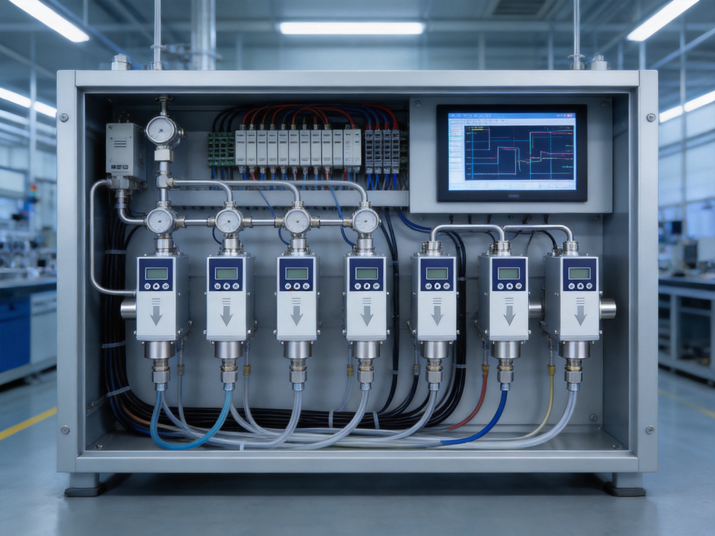
RS485 is robust for industrial environments because it supports differential signaling and multi-drop communication. Multiple instruments can often be connected on the same communication line, reducing cabling complexity in multi-channel gas control systems. This is useful in equipment such as gas mixing panels, test rigs, reactor platforms, calibration benches, environmental chambers, and automated process skids where several gas lines must be monitored and controlled simultaneously.
The product also supports standard 4 to 20 mA input and output control. The 4 to 20 mA current loop remains a preferred industrial signal because it resists electrical noise better than many voltage signals and can support long cable runs. For legacy systems, distributed control systems, and conventional PLC analog input modules, 4 to 20 mA compatibility greatly improves ease of adoption. Customizable 0 to 5 V and 0 to 10 V input and output control further expands compatibility with laboratory instruments, embedded controllers, and compact OEM equipment.
Local button operation provides another integration pathway. In early development, laboratory validation, or manual production equipment, operators may want to set the flow directly without a host controller. The LCD allows controlled and real-time flow rates to be displayed clearly, enabling immediate comparison between the set point and measured value. This makes the instrument convenient for both automated and semi-automated applications.
The combination of local interface, analog signals, and digital communication offers a layered integration model. A machine builder can use buttons during prototyping, analog signals during initial automation, and Modbus for advanced data acquisition and remote monitoring. This protects design investment because the same instrument can remain useful as the user’s control system becomes more sophisticated.
Gas Compatibility and Practical Use Cases
The product supports selectable gas types including air, nitrogen, oxygen, methane, argon, carbon dioxide, helium, hydrogen, and propane. These gases cover many common industrial and laboratory requirements. Nitrogen is frequently used for inerting, purging, blanketing, and process protection. Oxygen may be required for combustion support, oxidation processes, life science equipment, or gas blending systems. Argon is widely used in welding, shielding, and specialized manufacturing. Carbon dioxide appears in environmental testing, incubation, process gas control, and packaging. Helium and hydrogen are important for analytical instruments, leak detection, research systems, and energy-related equipment.
Because different gases have different thermal properties, selectable gas configuration is important in a thermal mass flow instrument. Proper gas selection helps ensure that the measurement algorithm matches the gas being controlled. For OEMs that build machines for different markets, this flexibility can reduce the number of product variants they need to manage.
Typical applications include clean gas supply control for analytical equipment, process gas regulation in small production equipment, gas flow control in test benches, inert gas purge control, burner gas and oxidant balancing where specifications permit, gas blending systems, coating and surface treatment equipment, environmental simulation devices, and research platforms. In each case, the product helps convert a desired gas flow value into controlled, measured, and documented gas delivery.
For small-flow applications, the SCCM ranges provide fine control over low gas quantities. This is useful in analytical instruments, microreactors, catalyst testing, sensor calibration, and laboratory gas dosing. For medium-flow applications, SLM ranges up to 300 SLM provide capacity for larger equipment, purge systems, and industrial processes. The availability of multiple range options allows the user to avoid oversizing, which is important because selecting a range that is too large can reduce practical low-end resolution.
Operating pressure requirements should be considered carefully during system design. The measurement working pressure range is 0 to 1.5 MPa. For control, pressure ranges vary by flow specification. For 10 SCCM to 30 SLM, the pressure range is 0.1 to 1.0 MPa. For 100 SLM, the pressure range is 0.1 to 0.65 MPa. For 300 SLM, the pressure range is 0.1 to 0.5 MPa. Normal operating pressure difference guidance includes 0.1 to 0.8 MPa for flow rates up to 30 SLM, 0.1 to 0.6 MPa for specifications above 30 SLM and up to 100 SLM, and 0.1 to 0.4 MPa for specifications above 100 SLM and below 300 SLM. For unconventional working pressure differences, customization consultation is available.
Mechanical Design, Installation, and Field Usability
The product uses standard mechanical interfaces including G1/4 and PT1/2 internal threads, with other threads available through customization. Standardized connection options reduce installation difficulty and make the device easier to incorporate into gas panels, equipment frames, and piping assemblies. For OEM machine builders, consistent mechanical interfaces help standardize drawings, fixtures, and assembly procedures.
Installation convenience is more than a minor detail. In industrial production, the cost of installation includes design time, assembly time, leak testing, commissioning, and long-term maintenance. A flow controller with a standard interface and integrated display reduces the number of adapters and external components. This can improve system reliability because every additional fitting or connection is a potential leak point.
The instrument’s IP40 protection level is suitable for protected equipment interiors, panels, benches, and controlled environments where direct water spray, dust accumulation, and heavy contamination are avoided. Users should install the product in an environment that meets the specified temperature and humidity conditions. The operating temperature range is minus 10 to 55 degrees Celsius, and the humidity condition is less than 95 percent relative humidity with no frost, ice, or condensation. Condensation should be prevented because moisture can affect electronics and may also influence gas flow behavior.
Clean gas use is important. Thermal mass flow sensors and precision proportional valves are designed for clean gases, and contamination such as oil mist, particles, liquid droplets, or corrosive components can degrade performance. Appropriate filtration, drying, and pressure regulation are recommended where process conditions require them. A stable upstream pressure source and suitable downstream piping design help the controller perform at its best.
During commissioning, technicians should confirm the gas type, flow range, standard temperature condition, pressure difference, analog scaling, communication address, and set point source. They should also verify that the selected range matches the intended process. For the most stable control, the instrument should operate within the recommended pressure difference and flow range, avoiding conditions where the valve is nearly fully closed or fully open for long periods.
Advanced Manufacturing Strengths Behind the Product
ASY Electronics (JiaXing) Co.,Ltd. is a high-tech enterprise focused on building smart factories of the future. Its mission emphasizes efficient, reliable, and green smart manufacturing. The company’s capabilities in data sensing and intelligent connectivity provide a strong foundation for products such as broadband power line carriers, wireless temperature monitoring systems, transmitters, flow meters, and automatic door controllers. This broader product background is important because modern flow meters are no longer isolated mechanical instruments; they are intelligent sensing and control nodes in industrial data systems.
The company’s experience in edge-layer hardware products supports the development of instruments that must function close to machines, production lines, and field devices. Edge-layer products require reliable electronics, practical communication interfaces, anti-interference design, and stable firmware. The AI-FC flow meter reflects this philosophy through its combination of MEMS sensing, digital signal processing, Modbus communication, analog input and output, local display, and proportional control algorithms.
Advanced manufacturing for a proportional valve controlled thermal gas mass flow meter requires more than assembling parts. It requires careful sensor selection, precision mechanical machining, controlled bypass channel design, electronic circuit reliability, firmware calibration, valve matching, and final performance testing. The bypass shunt must be manufactured consistently so that the relationship between sensing channel flow and main channel flow remains stable. The proportional valve must be matched to the flow range and pressure requirements. The electronics must process small sensor signals accurately while driving the valve reliably.
Calibration is a key manufacturing strength. Flow specifications are measured under defined reference conditions, including 25 degrees Celsius, 101.32 kPa, and dry air. Defined conditions help ensure traceability and consistency. A properly controlled calibration process allows each device to meet its stated accuracy and response characteristics. For users, this means that the product can be integrated into equipment with predictable performance rather than requiring extensive field correction.
Digital signal processing is another strength. Thermal flow sensing produces signals that must be converted into stable, meaningful flow readings. The device’s internal algorithms process the sensor output, compensate according to selected gas and standard conditions, calculate instantaneous and cumulative flow, and support the control loop. High-quality firmware contributes to repeatability, response, and usability. It also allows the same hardware platform to support multiple communication and control methods.
The company’s industrial data integration background also supports customization. Users may require special threads, voltage signal options, gas configurations, pressure conditions, or integration support. A manufacturer with in-house hardware and application engineering capabilities can respond more effectively to these requirements than a supplier focused only on reselling standard instruments. For OEM customers, this can shorten development cycles and improve the long-term stability of the supply chain.
Quality Control and Reliability Considerations
Reliability in a gas flow controller depends on both component quality and manufacturing discipline. The MEMS sensing element must provide stable zero behavior and fast response. The valve must open and close smoothly over many operating cycles. The housing and mechanical connections must maintain sealing integrity. The electronics must operate within the specified power and environmental conditions. The firmware must handle normal operation, set point changes, communication, and display functions predictably.
The use of an electromagnetic proportional valve with long service life and high sensitivity improves operational durability. In automated systems, valves may adjust repeatedly throughout production. A valve with poor sensitivity can cause hunting, overshoot, or slow correction. A valve with limited life can become a maintenance burden. By selecting a proportional valve suitable for precise modulation, the product improves both performance and ownership experience.
Zero-point stability reduces maintenance concerns. If a flow meter drifts at zero, operators may lose trust in readings and begin adding unnecessary offsets or manual corrections. Stable zero behavior supports clearer process interpretation. It is especially useful during purge completion, gas shutoff verification, low-flow recipe steps, and system standby conditions.
Repeatability within the measurement range is also essential. In manufacturing, repeatability often matters as much as absolute accuracy. If a process produces the same output every time under the same set point, users can build stable recipes and quality systems. The product’s emphasis on high accuracy and good repeatability supports production consistency.
The LCD display contributes to reliability by making errors easier to detect. If a controller is not following the set point, the operator can see the controlled flow and real-time flow directly. If cumulative consumption changes unexpectedly, the operator can investigate leaks, process changes, or incorrect settings. A visible interface reduces dependence on external diagnostic tools and improves field service efficiency.
Energy Efficiency and Sustainable Production
Gas consumption is a hidden cost in many factories. Compressed air, nitrogen, argon, helium, hydrogen, oxygen, and specialty gases all represent energy, material, or procurement cost. Inaccurate flow control can waste gas through excessive purge rates, oversized safety margins, unstable manual adjustment, and uncontrolled leakage. A precise mass flow controller helps reduce unnecessary gas usage by delivering the required quantity rather than an approximate manual setting.
For processes using expensive gases such as argon, helium, or high-purity gases, accurate control can produce measurable savings. Even for compressed air and nitrogen, improved control can reduce compressor load, generator demand, or cylinder replacement frequency. Cumulative flow display supports consumption tracking, enabling users to compare actual use between batches, shifts, machines, or recipes.
The product aligns with the concept of green smart factories because it combines sensing, control, and data output. Measurement alone identifies consumption; control actively reduces waste; communication enables monitoring and management. When connected to a supervisory system, flow data can support energy management, predictive maintenance, production optimization, and sustainability reporting.
Stable flow control also reduces scrap. If a process depends on gas composition, purge volume, or reaction atmosphere, poor flow stability may lead to defective products, rework, or process interruptions. By improving flow consistency, the instrument indirectly supports material efficiency and lower environmental impact.
System Design Recommendations
To obtain the best performance, users should select the correct flow range, gas configuration, and pressure conditions. The rated range should be chosen so that normal operation falls comfortably within the controllable span. If the selected range is too low, the process may exceed the instrument capacity. If the selected range is too high, low-flow resolution and control performance may not be optimal.
Pressure regulation is important. The proportional valve needs sufficient pressure difference to control flow, but excessive pressure or unstable pressure can affect control behavior. A stable upstream regulator, clean gas supply, and properly sized tubing help maintain performance. For higher flow specifications, users should follow the recommended pressure difference ranges and consult for unconventional conditions.
Gas cleanliness should be protected with filters where needed. Particles can affect the bypass channel or valve seat. Liquids and condensation should be avoided. If the gas source may contain moisture, oil, or particles, upstream treatment should be considered. In oxygen, hydrogen, methane, or propane applications, users should follow all applicable safety standards, material compatibility requirements, ventilation practices, and hazard assessments.
Electrical wiring should follow industrial best practices. RS485 lines should use suitable twisted pair cabling, termination where appropriate, and proper grounding strategy. Analog signals should be routed away from high-power switching devices when possible. The DC 24 V power supply should provide adequate capacity and stable voltage. Since the working power is 12 W, the power system should include suitable margin for startup and operation.
When using Modbus RTU, communication parameters such as address, baud rate, parity, and register mapping should be set consistently with the host controller. When using analog control, the scaling between set point and flow range should be verified. During commissioning, it is good practice to test several set points across the operating range, observe response time, confirm stability, and record baseline performance.
Why This Product Supports Smart Factory Development
Smart factories depend on accurate data and controllable process variables. Gas flow is often one of those variables, yet it is sometimes managed with manual regulators or simple indicators. Upgrading gas flow points to intelligent mass flow control improves visibility and control at the edge of the production system. The AI-FC instrument functions as both a sensing device and an actuator, making it a useful edge-layer component.
Its RS485 Modbus communication allows gas flow data to be collected by PLCs, industrial computers, gateways, or monitoring platforms. Its analog interfaces allow compatibility with existing control architectures. Its LCD and buttons support direct local interaction. This multi-mode usability makes it practical for gradual digital transformation. A factory can begin with local use and later integrate the same device into a broader data system.
For equipment manufacturers, the product can enhance machine value. Machines equipped with accurate digital gas flow control can offer better recipe management, higher repeatability, improved diagnostics, and stronger customer confidence. For end users, the product can support production optimization, traceability, gas consumption management, and maintenance planning.
The company’s broader expertise in industrial IoT communication solutions, smart grid-related communication products, wireless temperature monitoring, transmitters, and industrial controllers reinforces its ability to support connected manufacturing environments. A flow meter developed within this context is not only a measuring device; it is part of a larger vision of reliable sensing, intelligent connectivity, and efficient industrial operation.

Q&A Section
What is the main function of this proportional valve controlled thermal gas mass flow meter?
Its main function is to measure clean gas mass flow and actively control the flow to a target set point using an integrated electromagnetic proportional valve. It combines sensing, control, display, analog signals, and RS485 Modbus communication in one device.
How is it different from a standard thermal gas mass flow meter?
A standard thermal gas mass flow meter usually measures and outputs flow but does not directly regulate it. This product includes proportional valve control, allowing it to maintain a set flow automatically through closed-loop adjustment.
What accuracy does the product provide?
The product provides control accuracy of plus or minus 1.0 percent of set point and measurement accuracy of 1 percent of full scale under specified reference conditions.
What gases can be selected?
Selectable gas types include air, nitrogen, oxygen, methane, argon, carbon dioxide, helium, hydrogen, and propane. Correct configuration should be confirmed for each application.
What communication method is available?
The product supports RS485 communication with the standard Modbus RTU protocol, making it suitable for integration with PLCs, controllers, gateways, and industrial monitoring systems.
Can it be used without a PLC?
Yes. The instrument has an LCD and button operation, allowing local flow setting and observation. It can also be controlled through analog input or Modbus when connected to an automation system.
What analog signals are supported?
Standard configuration includes 4 to 20 mA input and output control. Customizable options include 1 to 5 V, 0 to 5 V, and 0 to 10 V depending on application requirements.
What flow ranges are available?
Available ranges include small-flow SCCM specifications from 0 to 10 SCCM up to 0 to 500 SCCM, and SLM specifications from 0 to 1 SLM up to 0 to 300 SLM, depending on model selection.
What is the typical control response time?
The typical control response time is less than 1.5 seconds to T90, while the measurement response time is less than 50 milliseconds.
What should users pay attention to during installation?
Users should confirm gas cleanliness, correct flow range, proper pressure difference, suitable mechanical connection, stable DC 24 V power supply, and correct communication or analog signal configuration. Condensation, particles, and unsuitable pressure conditions should be avoided.
References
1. Baker, R. C. Flow Measurement Handbook: Industrial Designs, Operating Principles, Performance, and Applications. Cambridge University Press.
2. Miller, R. W. Flow Measurement Engineering Handbook. McGraw-Hill.
3. Liptak, B. G. Instrument Engineers' Handbook: Process Measurement and Analysis. CRC Press.
4. ISO 14511. Measurement of Fluid Flow in Closed Conduits: Thermal Mass Flowmeters.
5. Modbus Organization. Modbus Application Protocol Specification.
6. Webster, J. G. Measurement, Instrumentation, and Sensors Handbook. CRC Press.
7. ASY Electronics (JiaXing) Co.,Ltd. Product technical materials for the AI-FC proportional valve controlled thermal gas mass flow meter.