

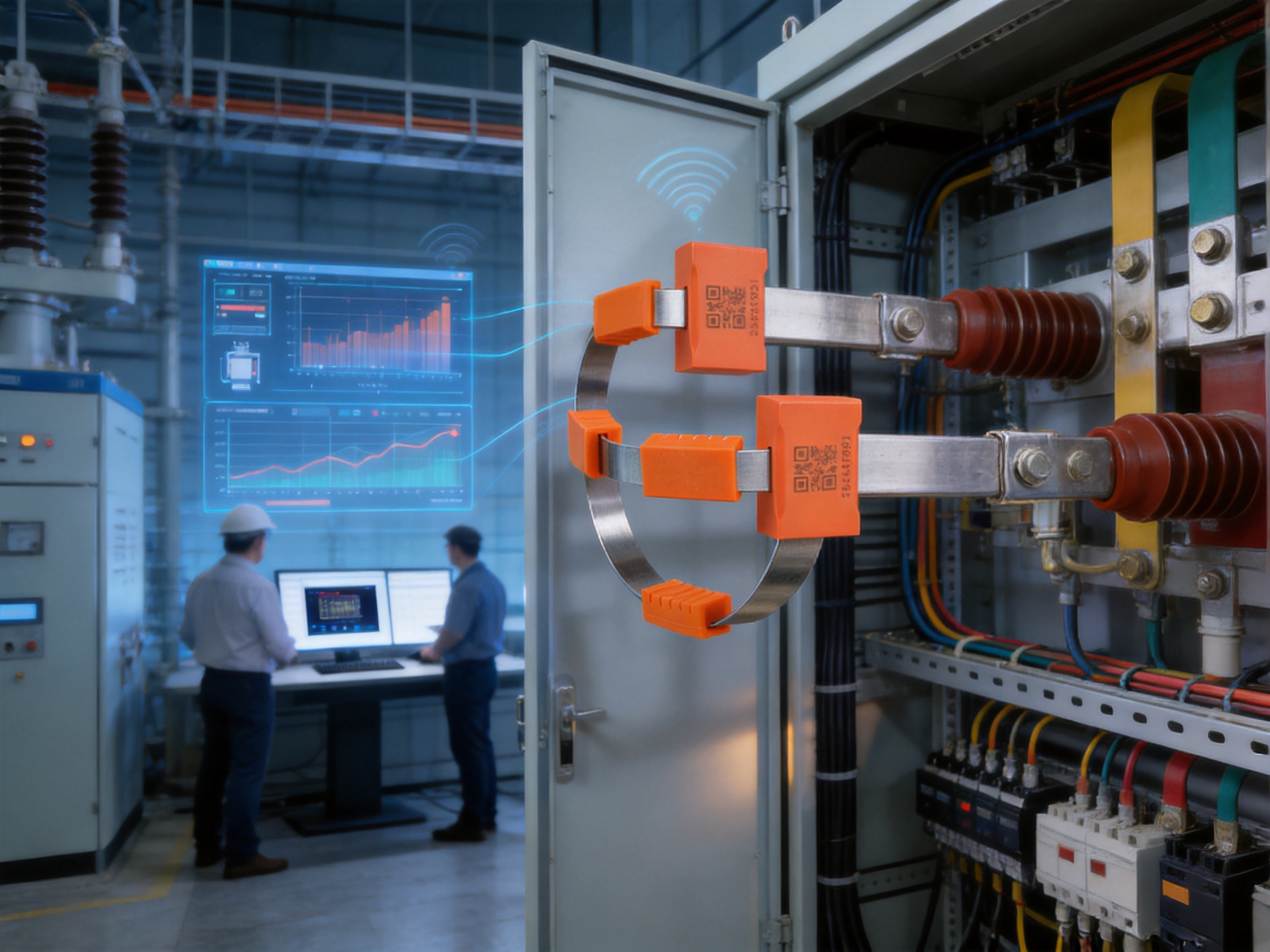
Introduction: A New Approach to Electrical Temperature Monitoring
Temperature is one of the most important indicators of electrical equipment health. Loose connections, overloaded conductors, deteriorated insulation, poor contact pressure, and abnormal current conditions often produce heat before they develop into visible failures. In switchgear and power distribution equipment, identifying these temperature changes at an early stage can help operators prevent equipment damage, unplanned outages, fire hazards, and costly maintenance events.
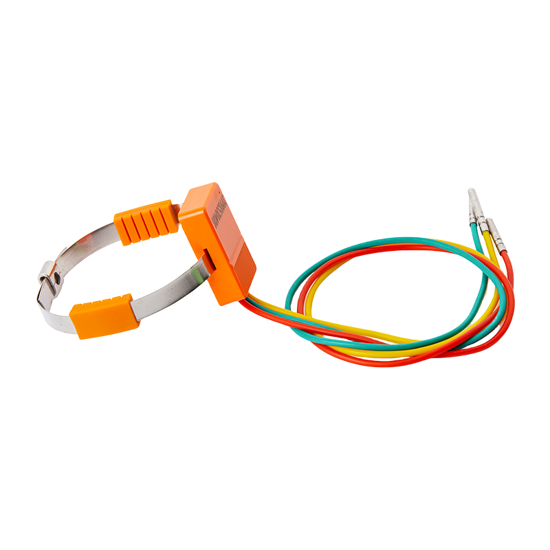
The KL-DS30WS3A passive wireless temperature measurement sensor is designed for continuous temperature monitoring in electrical installations where conventional wired sensors and battery-powered wireless sensors may be difficult to deploy. It combines temperature sensing, signal conditioning, logic control, wireless communication, and antenna technology in a compact strap-on module. Its most significant feature is its passive electromagnetic induction power supply. Instead of depending on an external power cable or a replaceable battery, the sensor obtains operating energy from the induced current surrounding the monitored conductor.
This design makes the sensor especially suitable for low-voltage switchgear, high-voltage switchgear, busbars, cable connections, circuit breaker terminals, tubular busbars, copper busbars, and substation terminals. Once installed, the sensor measures the temperature of the selected electrical component and transmits the collected data to a wireless temperature measurement host through a 433 MHz wireless network.
For industrial users, the product offers a practical balance of safety, installation simplicity, measurement accuracy, operating stability, and long-term maintenance efficiency. It is also supported by the engineering and manufacturing capabilities of ASY Electronics, a high-tech enterprise focused on industrial sensing, intelligent connectivity, smart grid applications, and industrial data integration.
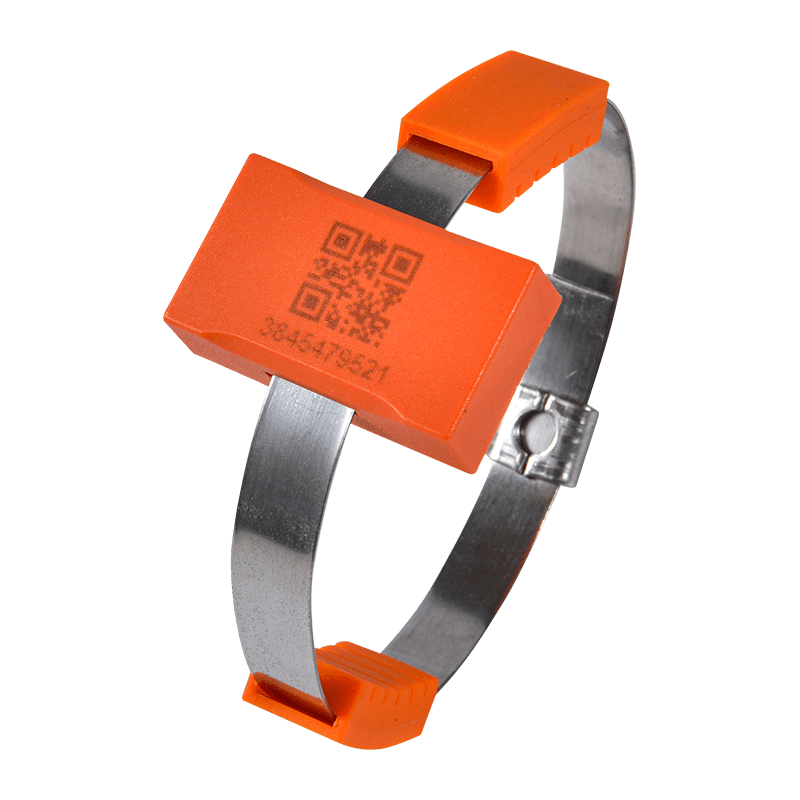
Passive Wireless Temperature Measurement Sensor
Product Overview
The KL-DS30WS3A is a single-channel passive wireless temperature sensor. Its integrated architecture includes a temperature sensor, signal modulation and amplification device, logic control circuit, wireless communication circuit, and antenna. These elements work together to detect the temperature at the installation point, process the measurement signal, and wirelessly transmit the result to a compatible host.
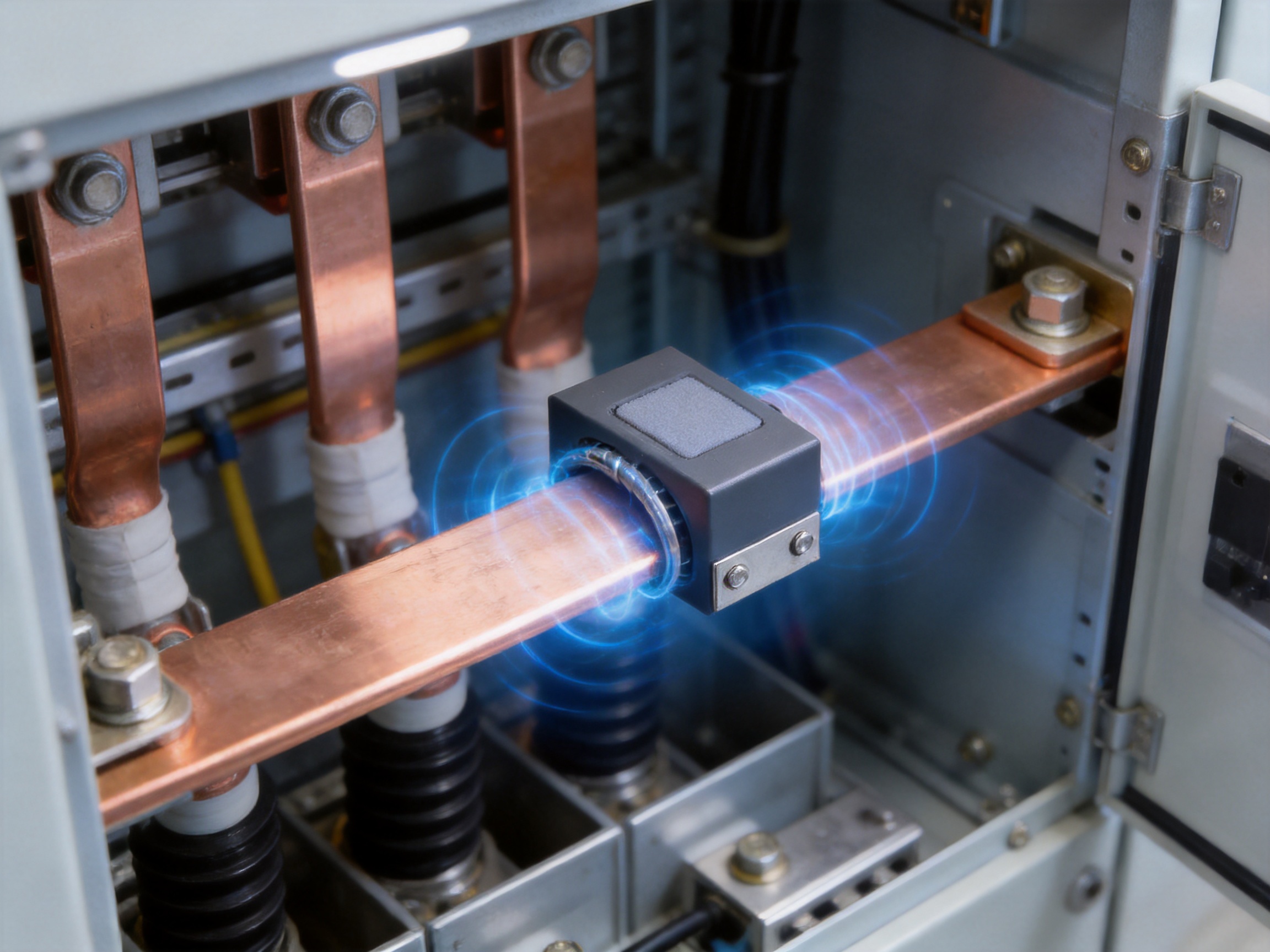
The sensor is powered by electromagnetic induction from the primary current path. When the monitored conductor carries sufficient current, the sensor extracts energy through a current-transformer-style induction structure. The specified operating condition is an induced current greater than 3 A, while the starting current is less than 5 A. This power method eliminates the need for a dedicated power supply and avoids the service burden associated with battery replacement.
The sensor uses a bundled mounting method. Its installation structure includes a power-collecting plate, soft silicone material, alloy plates, clips, and fastening screws. The temperature sensing position is placed directly against the component being monitored. This direct-contact arrangement helps the sensor respond to the actual temperature of the measured part rather than relying only on the surrounding air temperature.
With a measurement range of -40 to 150°C and an accuracy of ±1°C, the sensor can be used across a broad range of industrial operating conditions. Its standard temperature sampling interval is randomly selected between 10 and 30 seconds. This interval provides regular monitoring while limiting energy consumption, which is important for a device powered by induced current.
Wireless communication operates at 433 MHz, with a stated transmission distance of at least 350 meters in open space. Actual indoor distance depends on cabinet structure, metal shielding, building layout, electromagnetic conditions, antenna position, and the location of the wireless temperature measurement host. The sensor is therefore intended to be installed as part of a complete wireless monitoring system rather than evaluated only as an independent wireless device.
Core Technical Specifications
| Item | Specification |
|---|---|
| Product model | KL-DS30WS3A |
| Sensor type | Passive wireless temperature sensor |
| Measurement channel | Single channel |
| Temperature range | -40 to 150°C |
| Measurement accuracy | ±1°C |
| Sampling frequency | 10 to 30 seconds, random by default |
| Wireless frequency | 433 MHz |
| Wireless distance | At least 350 meters in open space |
| Power supply | Inductive power from the primary current path |
| Induced current requirement | Greater than 3 A for operating power |
| Starting current | Less than 5 A |
| Maximum installation voltage level | Up to 220 kV, subject to application assessment |
| Maximum primary current | Up to 5,000 A; higher currents require technical evaluation |
| Installation method | Bundled or strap-on installation |
| Main body dimensions | 24 mm × 22 mm × 10 mm |
How Passive Inductive Power Works
Traditional wireless temperature sensors normally use batteries. Although batteries provide convenient independence from wiring, they also introduce limitations. Battery capacity decreases over time, battery chemistry is affected by temperature, and replacement may require opening electrical cabinets or interrupting maintenance operations. In high-voltage equipment, even a simple battery replacement task may require strict safety procedures and significant labor.
The KL-DS30WS3A addresses this issue by drawing energy from the magnetic field generated by current flowing through the monitored conductor. The sensor's power-collecting structure is installed around the main current path. When the current reaches the required level, electromagnetic induction generates the energy needed for the sensor's sensing, processing, and wireless transmission functions.
This passive power architecture offers several important benefits. First, it reduces dependence on consumable batteries. Second, it avoids the need for an external low-voltage power cable routed into the switchgear. Third, it can simplify deployment in locations where wiring is physically difficult or electrically undesirable. Fourth, it allows the sensor to remain closely associated with the energized conductor that it monitors.
Because the sensor depends on induced current, application conditions must be checked before installation. The monitored conductor should normally carry an induced current greater than 3 A. The maximum specified primary current is 5,000 A, and installations exceeding this value require assessment by technical personnel. The voltage level at the installation location is specified as no more than 220 kV. These requirements help ensure that the energy-harvesting structure, insulation arrangement, physical clearance, and installation method are appropriate for the site.
The passive design does not mean that the sensor operates without any energy source. Instead, it means that the sensor obtains energy from the electrical environment in which it is installed. This is particularly advantageous for conductors that are continuously energized and carry sufficient load current. For circuits with very low or intermittent current, a site-specific evaluation is necessary to confirm stable operation.
Direct-Contact Temperature Measurement
Air temperature inside an electrical cabinet does not always represent the temperature of a busbar joint, cable terminal, or circuit breaker contact. A connection can develop excessive resistance and heat locally while the surrounding air remains within a normal range. For this reason, direct-contact measurement is valuable in predictive maintenance.
The KL-DS30WS3A uses a strap-on installation structure that places the sensing position against the measured component. The soft silicone part helps accommodate the contact surface and supports a more stable mechanical fit. During installation, the corrugated side of the soft silicone faces downward and aligns with the temperature sensing position. This arrangement helps maintain contact between the sensor and the monitored surface.
Direct contact offers a shorter thermal path than remote air measurement. When the measured object heats up, the sensor can detect the change more closely and provide useful information about the condition of the actual electrical connection. The method is suitable for monitoring areas where heat concentration may develop, including stationary contacts, cable connections, busbars, breaker terminals, and other current-carrying joints.
Correct installation remains essential. The sensor should be positioned so that the temperature sensing point contacts the intended measurement area. The alloy plates should be tightened evenly, the two ends should overlap under the clips, and the screws should be secured with an Allen wrench. A loose installation, poor contact, contamination, or incorrect positioning can affect thermal transfer and measurement reliability.
Applications in Switchgear and Power Distribution
Removable High-Voltage Switchgear
In removable high-voltage switchgear, the sensor can be installed on busbars, stationary contacts, cable connections, and other locations where abnormal temperature may indicate a developing fault. These components can be difficult to monitor with wired sensors because movable sections, confined spaces, and insulation requirements complicate cable routing.
A passive wireless sensor can reduce the amount of wiring introduced into the cabinet. It can also support monitoring of multiple locations when several sensors are connected to one wireless host. This approach allows operators to establish a temperature profile across important current paths and compare temperatures between phases or similar equipment positions.
Fixed High-Voltage Switchgear
Fixed high-voltage switchgear contains busbars, isolating switches, cable connections, and other high-energy components. Thermal abnormalities in these areas may be caused by loose fasteners, poor contact, oxidation, overload, installation defects, or long-term degradation. Continuous monitoring can help maintenance personnel detect rising temperature before a serious incident occurs.
The stated voltage application limit is up to 220 kV, subject to engineering assessment and correct installation practice. High-voltage installations require careful attention to clearance, insulation, mechanical fastening, cabinet design, and site safety procedures. The sensor should be installed only by qualified personnel following the equipment manufacturer's and system integrator's requirements.
Low-Voltage Switchgear
Low-voltage applications include outgoing terminals, circuit breaker input and output terminals, cable outlets, and distribution connection points. These locations are often exposed to changing loads and may experience localized heating due to loose terminals or uneven contact pressure.
The compact body size of 24 mm × 22 mm × 10 mm supports installation in confined switchgear spaces. Its strap-on structure can be adapted to various conductor and terminal arrangements, provided that the measured surface, conductor size, current level, and available clearance are suitable.
Busbars and Substation Terminals
Tubular busbars, copper busbars, and substation terminals are also suitable application targets. These components may carry high currents and can be distributed over large installations. Wireless monitoring reduces the need to route signal cables across equipment sections and can support centralized data collection.
In a substation or industrial distribution system, temperature information can be used alongside load current, voltage, protection status, and maintenance records. A temperature sensor does not replace electrical protection equipment, but it adds a valuable condition-monitoring layer that can improve maintenance decisions and asset visibility.
Advantages Compared with Conventional Sensor Technologies
Advantages over Wired Temperature Sensors
Wired sensors can provide reliable measurements, but installation may require signal cables, power cables, cable supports, terminal blocks, isolation components, and cabinet modifications. In high-voltage equipment, routing cables from energized components to an external monitoring system can increase installation complexity and create additional design considerations.
The KL-DS30WS3A communicates wirelessly and receives power through induction. This reduces the number of physical connections required at the measurement point. It can therefore be installed in locations where wired access is inconvenient, where moving equipment makes cables impractical, or where cabinet penetration should be minimized.
Wireless deployment can also lower the time required for retrofit projects. Existing switchgear may not have spare cable channels or suitable terminal positions. A strap-on passive device can often be integrated with less alteration to the original equipment, subject to safety and engineering approval.
Advantages over Battery-Powered Wireless Sensors
Battery-powered sensors are easy to install, but their batteries have finite service lives. High or low ambient temperatures can accelerate battery aging, and maintenance teams must eventually access the equipment to replace the battery. If many sensors are distributed across a facility, battery replacement can become a recurring operational cost.
The inductive power design of the KL-DS30WS3A removes the normal battery replacement cycle. As long as the monitored conductor provides sufficient current and the sensor is correctly installed, the device can continue to obtain operating energy from the electrical system. This supports a lower-maintenance monitoring architecture.
Battery-free operation is particularly useful in enclosed electrical cabinets, remote equipment rooms, industrial plants, substations, and other locations where routine physical access is inconvenient. It also reduces the number of battery disposal and inventory issues associated with large-scale sensor deployment.
Advantages over Non-Contact Ambient Monitoring
Ambient temperature sensors can identify general cabinet heating, but they may not detect the precise thermal behavior of an individual connection. The KL-DS30WS3A uses direct contact with the measured part, providing a more focused view of the temperature at the electrical connection or current path.
This makes the sensor useful for condition-based maintenance. A maintenance team can investigate a specific terminal or busbar connection rather than inspecting an entire cabinet without a clear indication of where the problem may be developing.
Advantages in Retrofit Projects
Many industrial facilities need to add monitoring to existing equipment without replacing complete switchgear assemblies. Retrofitting a wired system may require extensive design changes, while battery-powered systems create future maintenance obligations. A passive wireless sensor provides a third option: compact, local installation with wireless data transmission and inductive energy harvesting.
The sensor's bundled installation method can accommodate a range of electrical components. Its small body and fastening structure support integration into areas where larger monitoring devices would be difficult to fit. The design is especially relevant to modernization projects involving smart substations, digital distribution rooms, industrial energy management, and predictive maintenance programs.
Measurement Performance and Data Transmission
The sensor provides a temperature measurement range from -40 to 150°C. This range covers normal and abnormal thermal conditions encountered in many electrical distribution applications. The ±1°C accuracy specification supports practical monitoring, alarm configuration, trend analysis, and comparison among similar equipment points.
The default sampling frequency is 10 to 30 seconds, with the interval randomly selected. A randomized interval can help distribute wireless communication activity when multiple sensors operate in the same system. It may also reduce the risk that many devices transmit at exactly the same time. The appropriate data strategy should be selected according to the monitoring host, the number of sensors, the required alarm response, and the characteristics of the application.
Wireless communication uses the 433 MHz frequency band. This band is widely used for low-power industrial and monitoring applications. The specified open-space transmission distance is at least 350 meters. Inside switchgear rooms or substations, the effective range can be lower because metal enclosures, concrete walls, cable trenches, equipment arrangement, and electromagnetic interference influence propagation.
For this reason, system planning should include a wireless site survey. The position of the wireless temperature measurement host should be selected to maximize coverage and reliability. In large facilities, multiple hosts, repeaters, or carefully planned sensor groups may be necessary. The wireless network should also be evaluated under representative operating conditions rather than only in an empty building.
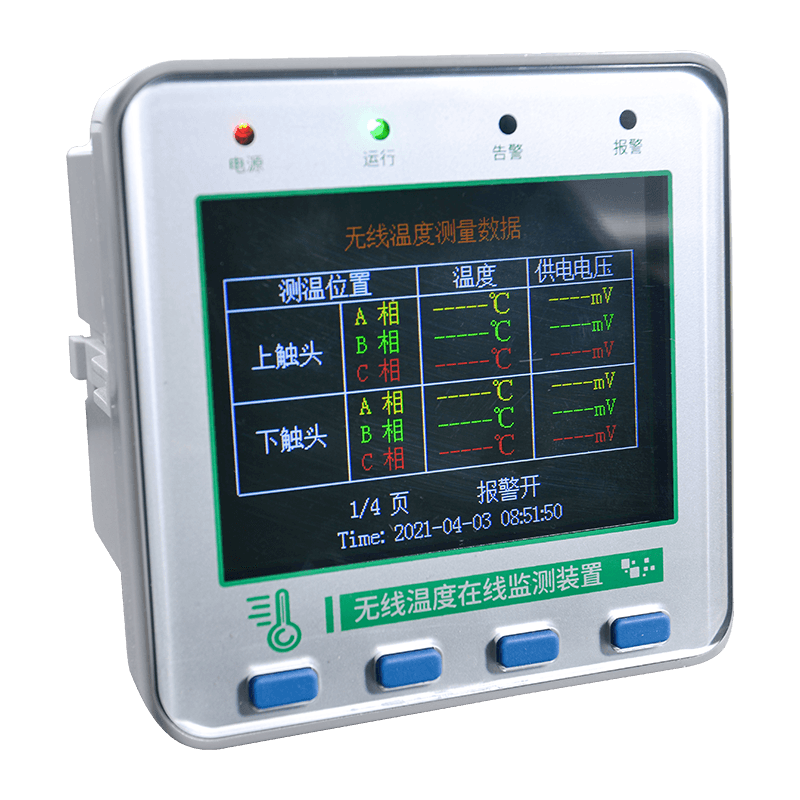
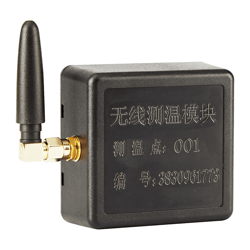
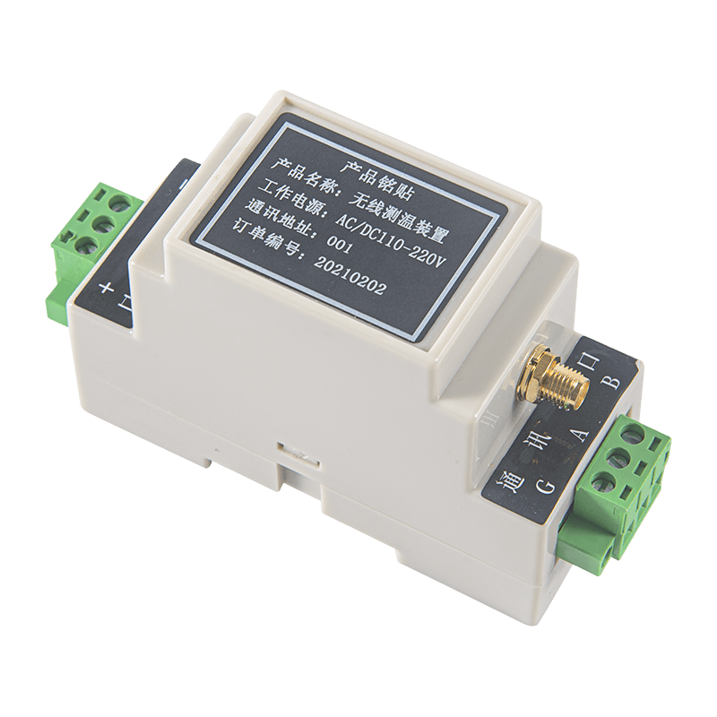
All data detected by the sensor is uploaded to the wireless temperature measurement host through wireless transmission. The host can serve as the collection point for temperature information from multiple monitoring locations. Depending on the overall system architecture, the data may then be used for local display, alarm management, historical trend analysis, or integration with a broader industrial monitoring platform.

Installation Method and Practical Procedure
Step One: Prepare the Installation Location
Before installation, qualified personnel should identify the exact component to be monitored and estimate the length required for the bundled installation. The selected location should have sufficient current for inductive power generation and enough physical clearance for the sensor, power-collecting plate, soft silicone, alloy plates, and fasteners.
The installer should confirm the voltage level, primary current, conductor shape, available space, and surface condition. The intended temperature sensing position should be clean and suitable for direct contact. Any site-specific safety procedures, shutdown requirements, insulation rules, and protective equipment requirements must be followed.
Step Two: Assemble the Sensor Structure
The appropriate length is inserted through the module. The power-collecting plate and soft silicone material are then inserted into the sensor. The corrugated side of the soft silicone should face downward, aligned with the temperature sensing position.
This orientation is important because the soft silicone and sensing structure must work together to maintain contact with the monitored object. The assembly should be checked before placement around the conductor to ensure that the sensing point is correctly positioned.
Step Three: Position the Sensor on the Current Path
The module is wrapped around the primary current path or power source. At the same time, the temperature measurement point should contact the component being measured. The sensor should not be positioned only near the component; it should be aligned so that the sensing point makes stable contact with the intended surface.
For busbars, cable connections, breaker terminals, or other conductive parts, the installer should choose a location that represents the thermal condition of the connection. If the objective is to identify terminal heating, the sensing position should be placed as close as practical to the terminal interface while maintaining required clearances.
Step Four: Tighten the Mechanical Assembly
The alloy plates on both sides are tightened to secure the module. The two ends are overlapped beneath the clips, and the screws are tightened with an Allen wrench. Fastening should be firm and uniform, but excessive force that could damage the assembly or the monitored component should be avoided.
After fastening, the installer should verify that the sensor cannot shift during normal equipment operation. The sensing point should remain in contact with the measured surface, and the power-collecting structure should remain properly positioned around the current path.
Step Five: Commission the Wireless Connection
Once the sensor is installed, the wireless temperature measurement host should be used to verify communication. The system should confirm that the sensor is identified correctly, that temperature data is received, and that the values are reasonable for the operating condition.
Commissioning should include a check of the sensor's self-reported power supply voltage value where supported by the monitoring system. The product includes a power supply voltage self-test function that detects the sensor's own power supply voltage in real time. This function can help identify insufficient induced energy or installation conditions that require adjustment.
Built for Industrial Reliability
Industrial temperature monitoring requires more than a temperature-sensitive component. It requires an integrated product that can operate in an electrical environment, extract energy safely and consistently, process signals accurately, communicate wirelessly, and remain mechanically stable after installation.
The KL-DS30WS3A integrates these functions into one compact module. The temperature sensor detects the measured condition. The signal modulation and amplification device processes the sensor output. The logic control circuit manages operating functions and measurement timing. The wireless communication circuit and antenna transmit data to the host. The inductive power structure provides operating energy without an external battery or power cable.
This integration reduces the need for multiple separate modules at the measurement point. A more compact architecture can simplify installation, reduce potential connection points, and make it easier to deploy multiple sensors in a limited cabinet space.
Reliability also depends on consistency in manufacturing. Small differences in sensor assembly, power-collecting components, fastening structures, antenna positioning, and electronic calibration can influence field performance. A professional industrial manufacturer must therefore control incoming materials, assembly procedures, soldering quality, mechanical dimensions, firmware loading, calibration, wireless communication, and final inspection.
Manufacturing Strengths and Engineering Capabilities
Integrated Hardware Development
ASY Electronics develops products around data sensing and intelligent connectivity. Its product portfolio includes broadband power line carriers, wireless temperature monitoring systems, industrial transmitters, thermal gas mass flow meters, and automatic door controllers. This combination of sensing and communication products provides a useful foundation for developing industrial monitoring devices.
The passive wireless sensor reflects this integrated capability. It is not merely a temperature probe. It combines an energy-harvesting structure, measurement circuit, signal conditioning, wireless communication, antenna design, mechanical mounting, and host-system compatibility. Experience across these technical areas helps support product optimization for real industrial environments.
Process Control for Compact Electronic Assemblies
A passive wireless sensor contains compact electronic and mechanical elements that must fit within a limited housing. Manufacturing processes should maintain dimensional consistency, secure component placement, clean assembly, and stable electrical performance. Process control is particularly important when the device must fit around conductors and maintain a defined thermal contact position.
Suitable production controls include standardized work instructions, fixture-assisted assembly, component traceability, visual inspection, electrical testing, and final functional verification. These measures help ensure that each sensor has consistent power extraction, temperature measurement, wireless communication, and mechanical installation characteristics.
Testing of Inductive Power Performance
Because the sensor is powered by induced current, production and quality testing should verify operation under representative current conditions. The device must be able to start within the specified starting-current requirement and continue operating when the monitored current provides sufficient induced energy.
Testing can include power-up behavior, operating voltage stability, transmission activity, and self-test reporting. These checks are valuable because a sensor that measures correctly but cannot maintain wireless communication under actual induced-power conditions would not meet the needs of a continuous monitoring system.
Temperature Calibration and Functional Verification
Temperature measurement accuracy is influenced by the sensing element, signal-conditioning circuit, assembly position, thermal contact design, and calibration process. A controlled calibration procedure helps verify the stated ±1°C accuracy across appropriate temperature points.
Functional verification should also confirm the sampling behavior, wireless data transmission, sensor identification, and power supply voltage self-test. By testing both measurement and communication functions, the manufacturer can evaluate the sensor as a complete industrial product rather than as an isolated electronic board.
Wireless Communication Testing
Wireless products require attention to antenna placement, radio-frequency performance, communication stability, and interference tolerance. The 433 MHz communication circuit and antenna should be checked during manufacturing and final inspection. Open-space distance is a useful reference, but industrial application testing should also consider metal cabinets and realistic installation conditions.
ASY Electronics' focus on intelligent connectivity supports the development of products intended to transfer field data into industrial monitoring systems. This experience can help customers plan complete deployments rather than purchasing isolated sensors without considering host communication and data integration.
Application-Oriented Customization
Industrial equipment varies significantly in conductor geometry, cabinet layout, current level, voltage class, environmental conditions, and monitoring objectives. A manufacturer with experience in industrial projects can help assess these factors before deployment.
For primary currents above 5,000 A, the product specifications call for technical assessment by the manufacturer's personnel. This requirement reflects the importance of application engineering. High-current installations may need evaluation of inductive coupling, thermal behavior, physical dimensions, insulation clearances, installation access, and wireless coverage.
Why Choose an Industrial IoT-Oriented Supplier
A temperature sensor becomes more valuable when it is part of a reliable information chain. The chain begins with sensing at the electrical component, continues through signal processing and wireless transmission, and ends with useful data for operators, maintenance teams, and facility managers.
ASY Electronics focuses on industrial IoT communication solutions, smart grid applications, and industrial data integration. Its broader product range includes power line carrier solutions and other industrial communication products. This background allows the company to approach monitoring projects from both the device and system perspectives.
For customers, this may simplify supplier coordination. Instead of treating sensing, communication, and industrial integration as entirely separate tasks, customers can work with a provider that understands field data acquisition and connectivity. This is especially useful in smart factory projects where equipment condition monitoring and energy management are connected parts of one digital strategy.
The company also positions itself as a manufacturer capable of supporting customized industrial solutions. Customization may involve installation structures, communication arrangements, monitoring configurations, project quantities, or integration requirements. Any customization should be evaluated against electrical safety, measurement performance, wireless compatibility, and production feasibility.
Maintenance and Operational Benefits
Continuous temperature monitoring supports a shift from reactive maintenance to condition-based maintenance. Instead of waiting for a failure or relying only on periodic manual inspections, operators can review temperature values over time and identify unusual changes.
A gradual temperature increase may indicate a connection that is loosening, aging, oxidizing, or carrying an abnormal load. A temperature difference between similar phases may indicate an imbalance or local connection issue. A sudden rise may require immediate investigation, particularly if it occurs together with a load change or protection event.
The sensor does not independently diagnose every possible fault. Temperature should be interpreted together with current, voltage, equipment status, environmental conditions, and maintenance history. However, reliable temperature data can help maintenance personnel prioritize inspections and focus on the most relevant components.
The battery-free structure can also reduce lifecycle maintenance. There is no routine battery replacement schedule for the sensor itself, although the device and installation should still be inspected as part of an electrical maintenance program. Mechanical fastening, wireless communication, thermal contact, and host data reception should be checked at appropriate intervals.
Deployment Planning for Large Facilities
A successful monitoring project begins with an application survey. The facility owner should identify critical equipment, known failure points, load profiles, access limitations, required alarm response times, and communication paths to the monitoring host.
Sensor locations should be selected according to risk and value. High-priority points may include main incoming connections, heavily loaded outgoing terminals, breaker input and output terminals, busbar joints, cable terminations, stationary contacts, and locations with a history of overheating.
The number and position of wireless hosts should be planned according to cabinet density and building structure. The open-space transmission specification is a useful reference, but metal enclosures and reinforced structures can reduce effective range. A practical deployment may require field testing, host repositioning, or additional communication equipment.
Sampling intervals should also match the application. A 10- to 30-second default interval is suitable for regular monitoring, but the overall system should determine how frequently data is displayed, stored, analyzed, and used for alarms. Large deployments should consider data volume, wireless traffic, host capacity, and long-term storage requirements.
Operators should define temperature warning levels based on the equipment design and operating conditions. A universal alarm value may not be appropriate for every conductor, insulation system, connection type, or ambient environment. Alarm policies should distinguish between warning, high-temperature, rapid-rise, and communication-loss conditions where the monitoring platform supports these functions.
Safety and Application Considerations
Installation on electrical equipment must be performed by qualified professionals. The sensor is designed for industrial use, but its presence does not eliminate the hazards associated with energized conductors and high-voltage equipment. Site safety rules, lockout and isolation procedures, personal protective equipment, clearance requirements, and equipment-specific instructions must always be followed.
The specified installation voltage level is no more than 220 kV, and the primary current is no more than 5,000 A unless technical personnel evaluate a higher-current application. These limits should be treated as design parameters, not as permission to install the sensor without engineering review.
Users should verify that the mechanical installation does not interfere with breaker movement, isolation operations, inspection access, insulation systems, ventilation, or enclosure closing. The sensor should not obstruct moving components or create an unintended path for mechanical stress.
Environmental conditions should also be considered. The temperature range is -40 to 150°C, but the complete installation must account for humidity, condensation, dust, vibration, chemical exposure, enclosure protection, and long-term thermal cycling. Where these conditions are severe, the manufacturer or project engineer should confirm suitability before deployment.
Product Value for Smart Factories and Smart Grids
Smart factories require dependable data from physical equipment. Without accurate field data, digital platforms cannot provide meaningful condition monitoring or energy analysis. Passive wireless temperature sensors provide a practical way to add measurement points to existing electrical infrastructure.
In a smart factory, the sensor can support monitoring of distribution panels, production-line switchgear, motor control centers, and other electrical assets. In a smart grid or substation environment, it can help improve visibility of busbars, terminals, cable connections, and switching equipment.
Temperature information can also contribute to energy management. A hot connection may represent not only a safety concern but also a source of electrical loss. Detecting and correcting abnormal resistance can improve equipment efficiency and reduce the risk of progressive deterioration.
When combined with industrial transmitters, flow measurement devices, power line communication products, and automatic control systems, wireless temperature monitoring can become part of a larger industrial data architecture. The result is a more connected facility in which equipment status, energy use, process variables, and maintenance information can be reviewed through a coordinated system.
Quality, Stability, and Total Cost of Ownership
The purchase price of a sensor is only one part of its economic value. Customers should also consider installation labor, wiring materials, battery replacement, equipment downtime, inspection requirements, communication infrastructure, and the potential cost of undetected electrical faults.
The KL-DS30WS3A can reduce several recurring costs through passive power operation and wireless installation. It does not require a dedicated battery replacement program, and it can reduce the quantity of signal wiring at the measurement point. Its direct-contact structure can also help generate more actionable data than general ambient monitoring.
Long-term value depends on product quality and system reliability. A sensor that frequently loses communication or shifts away from the measured surface will not provide dependable maintenance information. Manufacturing controls, functional testing, application support, and installation guidance are therefore important parts of the total solution.
As an industrial IoT manufacturer, ASY Electronics combines product development with application-oriented engineering. Its experience in sensing and industrial communications provides a foundation for supporting customers from product selection through deployment and system integration.
Frequently Asked Questions
What is the KL-DS30WS3A?
The KL-DS30WS3A is a single-channel passive wireless temperature measurement sensor designed for electrical equipment monitoring. It measures the temperature of a directly contacted component and transmits data wirelessly to a temperature measurement host.
Does the sensor use a battery?
No. The sensor obtains operating power through electromagnetic induction from the primary current path. The specified induced current requirement is greater than 3 A.
Where can the sensor be installed?
Typical locations include removable and fixed high-voltage switchgear, low-voltage switchgear, busbars, stationary contacts, cable connections, circuit breaker input and output terminals, tubular busbars, copper busbars, and substation terminals.
What temperature range can it measure?
The specified temperature measurement range is -40 to 150°C, with a measurement accuracy of ±1°C.
How often does the sensor sample temperature?
The default sampling frequency is 10 to 30 seconds, with the interval randomly selected within that range. The practical monitoring configuration depends on the host system and application requirements.
What wireless frequency does it use?
The sensor uses 433 MHz wireless communication. The stated transmission distance is at least 350 meters in open space. Indoor and switchgear-room performance depends on the building and equipment environment.
What is the maximum current for installation?
The specified primary current requirement is up to 5,000 A. Applications above 5,000 A should be evaluated by the manufacturer's technical personnel before installation.
Can it be used in high-voltage applications?
The stated voltage level requirement for the installation location is no more than 220 kV. High-voltage installation must be reviewed and performed by qualified personnel following applicable safety and engineering requirements.
How is the sensor mounted?
It uses a bundled or strap-on mounting method. The module is wrapped around the primary current path, the temperature sensing point is placed against the measured component, and the alloy plates and screws are tightened to secure the assembly.
Does direct contact improve the measurement?
Direct contact helps the sensor measure the temperature of the selected electrical component rather than only the surrounding air. Correct positioning and secure fastening are essential to maintain effective thermal contact.
What does the power supply voltage self-test do?
The self-test function detects the sensor's own power supply voltage value in real time. This can help confirm that the induced power available at the installation point is sufficient for stable operation.
Who should install the sensor?
Installation on electrical equipment should be completed by qualified professionals who understand electrical safety, switchgear construction, high-voltage clearances, and the relevant site procedures.
What support can the manufacturer provide?
ASY Electronics can support industrial sensing and communication projects through product development, application evaluation, wireless monitoring solutions, smart grid technologies, and industrial data integration. High-current or unusual installations should be reviewed with the manufacturer's technical personnel.
Conclusion
The KL-DS30WS3A passive wireless temperature measurement sensor provides a practical solution for monitoring electrical connections and current-carrying components. Its combination of direct-contact sensing, inductive power extraction, wireless transmission, compact dimensions, and industrial temperature performance addresses several limitations of conventional wired and battery-powered sensors.
By drawing energy from the monitored conductor, the sensor eliminates the normal battery replacement cycle and reduces the need for external power wiring. Its bundled installation structure supports retrofit projects and confined switchgear spaces. Its 433 MHz wireless communication and open-space transmission distance of at least 350 meters support flexible data collection when the host and network are properly planned.
The product is also strengthened by the broader capabilities of ASY Electronics in industrial IoT communication, smart grid solutions, sensing technology, and data integration. Through controlled manufacturing, functional testing, application engineering, and system-oriented development, the company can support customers seeking reliable condition-monitoring solutions for smart factories, substations, power distribution systems, and industrial facilities.
For organizations aiming to improve electrical safety, reduce unplanned downtime, and build more connected maintenance programs, passive wireless temperature monitoring offers an effective foundation. When correctly installed and integrated with a suitable host system, the KL-DS30WS3A can transform localized temperature information into actionable industrial intelligence.
References
1. Product technical information for the KL-DS30WS3A Passive Wireless Temperature Measurement Sensor, including operating range, wireless specifications, installation method, and application areas.
2. Industrial switchgear condition-monitoring principles for detecting abnormal heating at busbars, cable connections, terminals, and circuit breaker contacts.
3. General engineering practices for electromagnetic induction power harvesting in current-carrying electrical equipment.
4. General guidance on wireless sensor deployment in metal enclosures, substations, industrial plants, and smart-grid environments.
5. Industrial IoT system design principles for equipment condition monitoring, intelligent connectivity, energy management, and predictive maintenance.
6. Electrical installation safety practices for qualified personnel working with low-voltage and high-voltage switchgear.