

Industrial gas measurement is becoming increasingly important as factories pursue safer operations, lower energy consumption, tighter process control, and more connected production systems. In applications involving clean gases, compressed air, inert gases, laboratory gases, process gases, and other low-flow media, the measuring instrument must provide more than a basic flow reading. It must deliver stable performance, high sensitivity, reliable communication, convenient installation, and dependable operation in demanding environments.
The AI-FK explosion-proof thermal gas mass flow meter is designed to address these requirements through a compact MEMS-based sensing system, industrial communication functions, multiple output options, and intrinsically safe explosion-proof construction. It is intended for accurate measurement and control of small gas flow rates while reducing the need for complicated temperature and pressure compensation. With a measurable range from 0.3 NL/min to 3000 NL/min, it can serve applications ranging from low-flow laboratory and analytical systems to industrial gas distribution and equipment monitoring.
Unlike many traditional volumetric or differential-pressure flow meters, this thermal mass flow meter directly applies thermal sensing technology to gas measurement. This enables a responsive and practical solution for systems where low-flow sensitivity, repeatability, and real-time data access are essential. The instrument also combines local display, 4–20 mA output, RS485 communication, Modbus RTU protocol, and a configurable PNP output in one integrated platform.
This article examines the product’s operating concept, technical advantages, industrial applications, safety characteristics, connectivity, installation considerations, and the manufacturing strengths behind its development. It also explains why a specialized industrial electronics manufacturer with capabilities in sensing, edge hardware, communications, and data integration can provide greater value than a supplier focused only on conventional flow measurement.
Product Overview
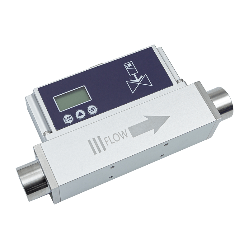
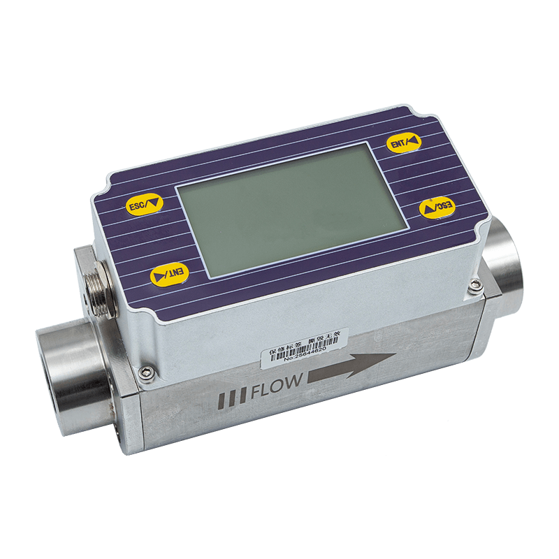
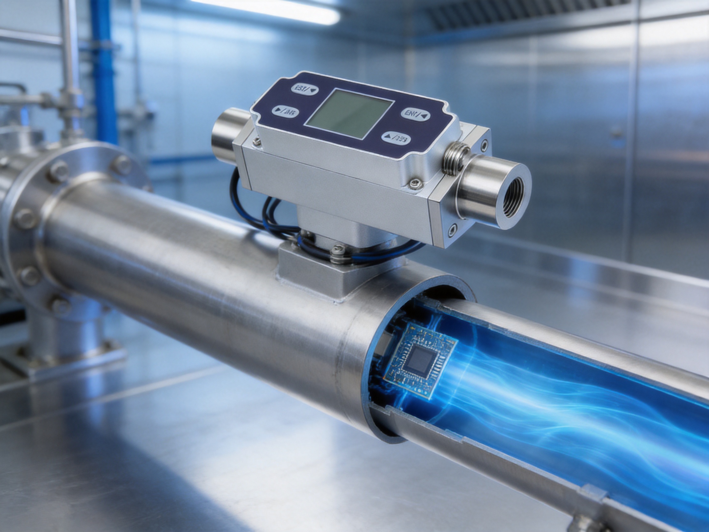
The AI-FK is an explosion-proof thermal gas mass flow meter developed for clean-gas measurement in industrial and commercial environments. Its principal sensing element is an advanced microelectromechanical system, commonly known as a MEMS, flow sensing chip. MEMS technology enables the sensing structure to be manufactured in a compact and highly repeatable form while maintaining high sensitivity to gas movement.
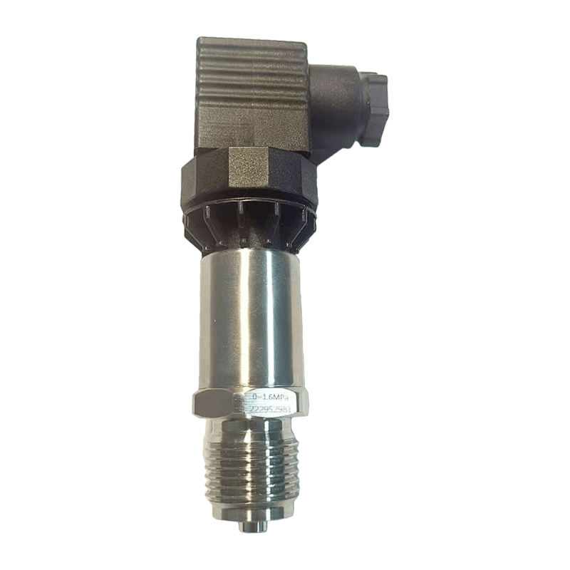
The instrument is powered by a DC24V supply and has a rated power consumption of 2.5 W. Its stated accuracy is ±1.5% of full scale, and its medium-temperature operating range is -10°C to 50°C. The default working pressure is up to 1.6 MPa, with higher-pressure versions and integrated pressure measurement available as customization options.
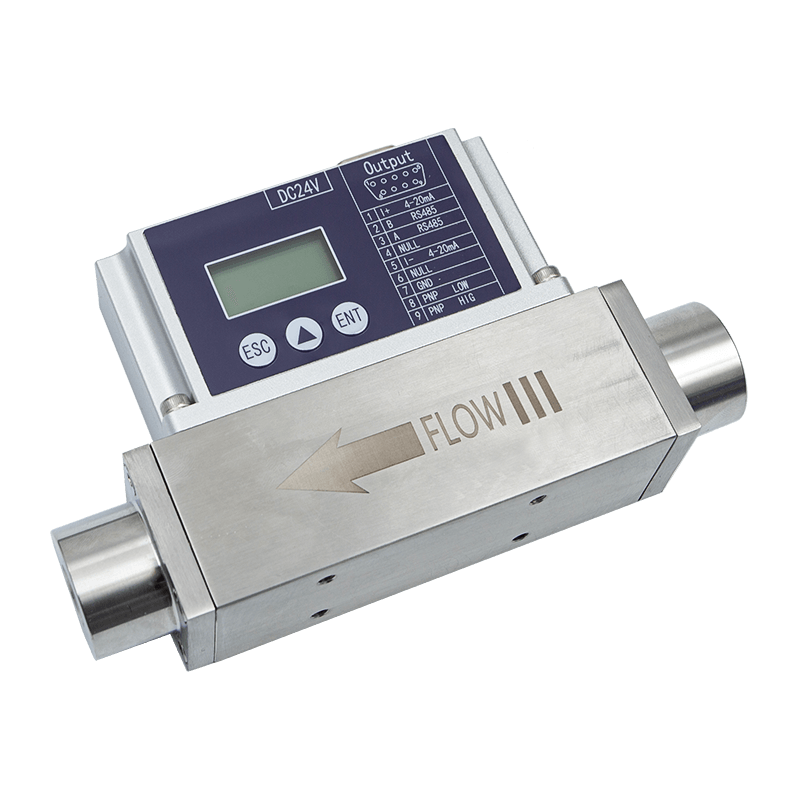
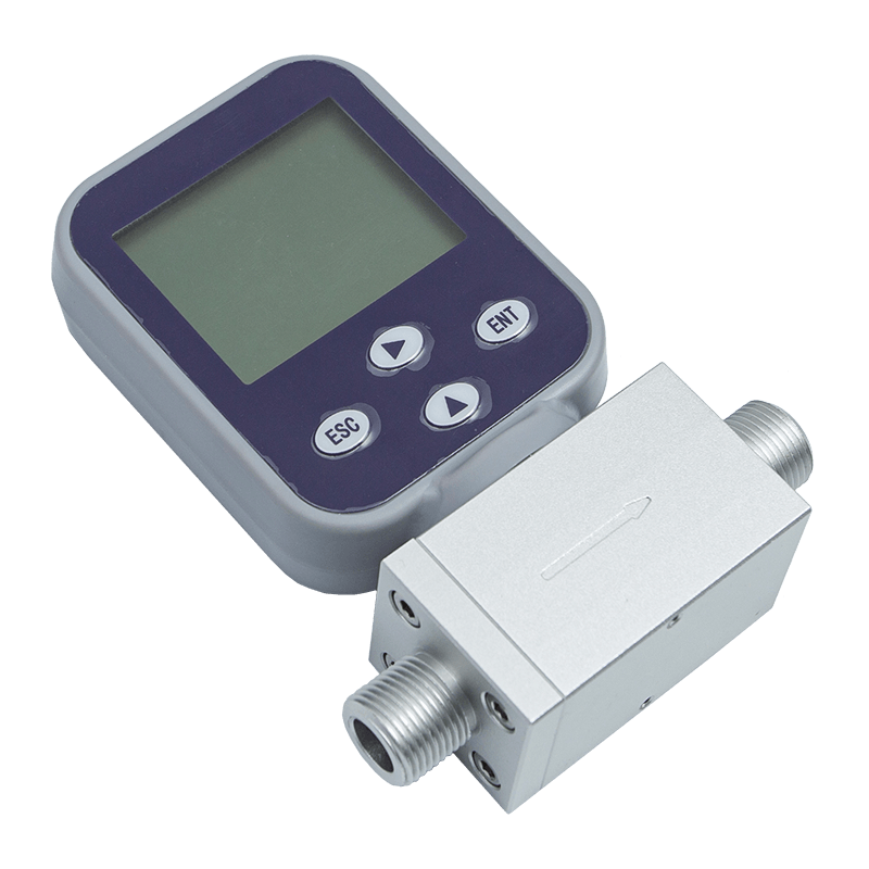
Mechanical connections can be supplied with BSPT internal thread or G internal thread configurations. This gives system designers flexibility when integrating the instrument into different piping standards and equipment layouts. The device also provides a local LCD display for instantaneous and cumulative flow, which allows operators to inspect operating conditions without relying exclusively on a remote control system.
For automation and industrial networking, the meter provides a standard 4–20 mA current output and RS485 communication using the Modbus RTU protocol. One PNP output is also available, with options for PNP pulse output or 0–5 V and 0–10 V voltage output depending on application requirements. This combination allows the meter to be connected to PLCs, distributed control systems, remote I/O modules, industrial gateways, energy management platforms, and supervisory software.
Core Operating Principle
Thermal gas mass flow measurement is based on the relationship between heat transfer and gas movement. A sensing element is heated, and the flow of gas carries heat away from the sensing area. The amount of heat transferred depends on the velocity, thermal properties, and mass movement of the gas. By monitoring the thermal response, the instrument can calculate the flow rate.
This approach differs from differential-pressure measurement, which typically requires a restriction such as an orifice plate, nozzle, or venturi tube. Differential-pressure systems calculate flow from the pressure difference created by the restriction. Although that technology is widely used, it can introduce permanent pressure loss and may require additional pressure and temperature compensation.
Thermal mass measurement is particularly useful for clean gases and low-flow applications. Because the sensing method responds directly to the thermal behavior of the gas, the meter can measure small flow rates with high sensitivity. It can also simplify system design by reducing the need for separate compensation devices in applications where the specified operating conditions are suitable.
The MEMS sensing chip contributes to compact construction, stable response, and consistent production. Modern MEMS manufacturing can create precisely defined sensing structures in a repeatable format, helping reduce variation between sensors. When combined with signal processing and calibration, this architecture supports the product’s stated accuracy and repeatability within its measurement range.
The instrument is designed for measurement under reference conditions of 25°C, 101.32 kPa, and dry air. Users should therefore confirm the selected gas type, reference condition, pressure, temperature, and installation arrangement before finalizing a system design. Where special gases or unusual process conditions are involved, customization and application review are recommended.
Key Technical Specifications
| Parameter | Specification |
|---|---|
| Product type | Explosion-proof thermal gas mass flow meter |
| Model | AI-FK |
| Power supply | DC24V / 2.5 W |
| Accuracy | ±1.5% of full scale |
| Medium temperature | -10°C to 50°C |
| Storage temperature | -10°C to 65°C |
| Working pressure | Up to 1.6 MPa by default |
| Minimum measurable flow | 0.3 NL/min |
| Maximum measurable flow | 3000 NL/min |
| Standard output | 4–20 mA |
| Communication | RS485, Modbus RTU |
| Display | Instantaneous and cumulative flow |
| Mechanical connection | BSPT internal thread or G internal thread |
| Response time | 50–1000 ms |
| Humidity | Less than 95% RH, without frost or ice |
| Optional functions | Temperature measurement, pressure measurement, higher-pressure configurations, customized output |
The specification range makes the AI-FK suitable for both small-flow and medium-flow gas applications. The lower limit of 0.3 NL/min is useful for systems that require detection and regulation of very small gas quantities. The upper limit of 3000 NL/min allows the same product family to be considered for larger industrial branches, equipment supply lines, and centralized gas distribution systems.
The response time can range from 50 ms to 1000 ms, depending on configuration and application conditions. A fast response can be valuable for control loops, leak detection, burner adjustment, gas switching, and equipment protection. A slower filtered response may be preferable in applications where the gas flow is unstable and operators need a smoother displayed value.
Advantages of MEMS Thermal Sensing
High Sensitivity at Low Flow Rates
One of the main advantages of MEMS thermal sensing is sensitivity to small gas movement. Traditional flow meters may become less effective when the flow falls near the bottom of their range. A thermal sensing chip can detect the heat-transfer changes associated with small flow rates, allowing the meter to monitor low-flow conditions that are important in laboratories, gas cabinets, process tools, calibration systems, and precision equipment.
The minimum measurable flow of 0.3 NL/min demonstrates the instrument’s suitability for applications where small variations in gas consumption must be identified. This can help operators detect abnormal consumption, confirm valve operation, verify purge sequences, and recognize possible leakage before it develops into a larger operational problem.
No Requirement for a Large Mechanical Restriction
Many differential-pressure instruments require a restriction to generate a measurable pressure difference. This can cause pressure loss and may affect the efficiency of a gas delivery system. A thermal mass flow meter does not depend on the same type of permanent restriction, helping reduce the impact on the process line.
Lower pressure loss can be beneficial in compressed-air systems, clean-gas distribution, analyzer supply lines, and equipment with limited upstream pressure. It can also help reduce the need to oversize compressors or pressure regulators to compensate for measurement-related losses.
Reduced Compensation Complexity
Conventional volumetric flow measurement often requires temperature and pressure correction when process conditions change. The AI-FK is designed to measure gas mass flow without requiring temperature and pressure compensation for suitable applications. This can simplify installation and reduce the number of separate instruments required in a basic flow-monitoring point.
However, application conditions still matter. Gas type, pressure, temperature, humidity, contamination, and flow profile can all influence measurement performance. The meter can be customized with temperature and pressure measurement functions when the application requires additional process information or advanced compensation.
Stable Zero Point
Zero-point stability is essential in low-flow measurement. If a meter produces an unstable zero reading, it may report false consumption, create nuisance alarms, or cause unnecessary control actions. The product is designed with attention to sensor zero-point stability and specifies a zero drift of ±20 mV.
Stable zero behavior improves confidence during shutdown conditions and helps operators distinguish between genuine low flow and instrument noise. It is particularly useful in systems that use accumulated flow data for production accounting, energy management, or maintenance planning.
Strong Anti-Interference Capability
Industrial environments may contain electromagnetic noise from motors, variable-frequency drives, switching power supplies, contactors, welding equipment, and communication systems. The AI-FK’s sensing and signal-processing architecture is designed to provide strong anti-interference capability, supporting more reliable operation in electrically active facilities.
Correct wiring, grounding, shielding, power-quality management, and installation practices remain important. Nevertheless, an instrument designed for industrial interference conditions gives system integrators a stronger starting point than a general-purpose sensor intended for benign laboratory environments.
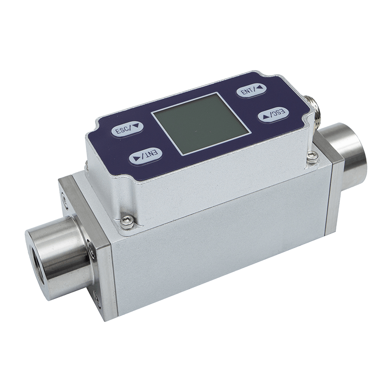
Explosion-Proof Type Thermal Gas Mass Flowmete
Explosion-Proof and Intrinsically Safe Design
Gas measurement equipment may be installed in areas where flammable or combustible materials are present. In such locations, electrical equipment must be selected and installed according to the applicable hazardous-area classification, local regulations, and project safety requirements. The AI-FK is described as having intrinsically safe explosion-proof certification, making it suitable for applications that require a certified explosion-proof measurement device.
Intrinsically safe design generally focuses on limiting electrical energy, thermal energy, and possible ignition sources to levels that cannot ignite a specified hazardous atmosphere under the relevant certification conditions. This requires careful design of circuits, enclosure interfaces, power requirements, signal connections, and installation arrangements.
Users must verify the exact certification marking, gas group, temperature class, protection level, permitted installation zone, wiring method, and associated safety barriers before deployment. Certification is not a substitute for correct system engineering. The complete installation must comply with the applicable national and regional standards, site safety rules, and hazardous-area procedures.
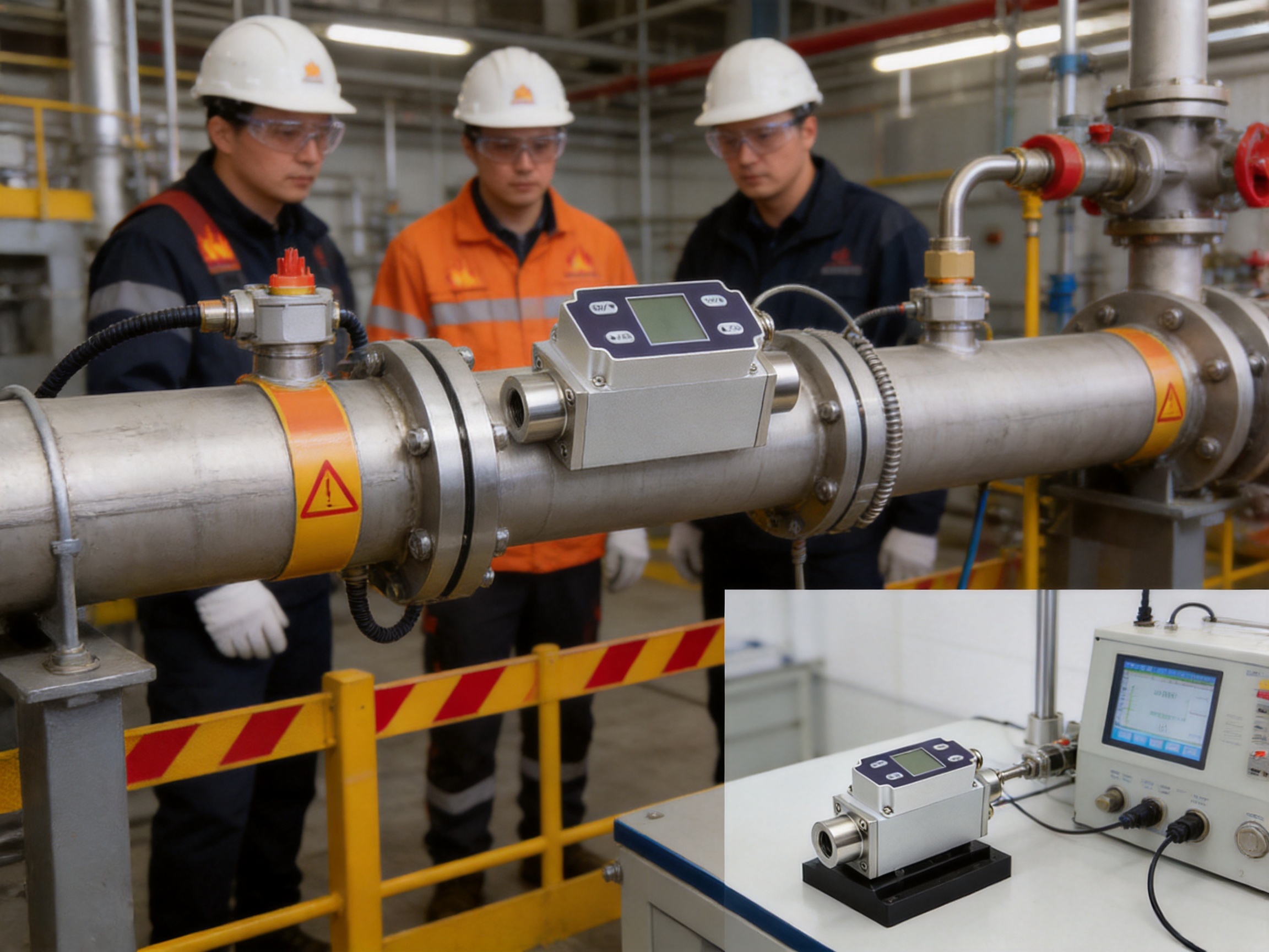
The explosion-proof configuration expands the range of possible applications compared with ordinary non-certified flow sensors. It can be considered for gas supply rooms, industrial process areas, chemical production support systems, fuel-related equipment, gas monitoring cabinets, and other locations where safety certification is essential.
A certified explosion-proof product can also reduce the engineering burden for customers. Instead of developing a custom protective enclosure around a general-purpose sensor, the system designer can begin with an instrument created for hazardous industrial conditions. This may simplify documentation, equipment selection, risk assessment, and maintenance planning.
Industrial Communication and Smart Factory Integration
Modern flow measurement is no longer limited to a local display. Industrial facilities increasingly require field data to be shared with control systems, production databases, energy platforms, and remote diagnostic tools. The AI-FK supports this transition through 4–20 mA output and RS485 communication with Modbus RTU.
4–20 mA Output
The 4–20 mA signal remains one of the most widely used industrial analog standards. It is compatible with PLC analog input modules, distributed control systems, process controllers, data acquisition equipment, and industrial transmitters. The current-loop format is valued for its relative resistance to voltage drop and its ability to communicate over considerable cable distances when correctly installed.
The signal can represent the instantaneous flow value across the configured measurement range. In many systems, the 4 mA level represents the lower range value and 20 mA represents the upper range value. The specific scaling, alarm behavior, and fault-current configuration should be confirmed during commissioning.
RS485 and Modbus RTU
RS485 is a practical physical-layer standard for industrial multi-device communication. It allows multiple instruments to share a communication bus when the network is correctly terminated and addressed. Modbus RTU is widely supported by PLCs, gateways, human-machine interfaces, industrial computers, and building or energy management systems.
Through digital communication, users can access instantaneous flow, cumulative flow, status information, and other available parameters without adding separate analog conversion hardware. Digital data can improve measurement transparency, simplify wiring, and support centralized monitoring across many production lines.
For large factories, the communication function can contribute to a broader industrial IoT architecture. Flow data may be collected at the edge, combined with equipment status, and transferred to a plant-level platform. This can support consumption analysis, abnormal-flow alarms, production traceability, predictive maintenance, and resource optimization.
Flexible Auxiliary Output
The standard PNP output can be used for pulse counting, threshold alarms, or event signaling. Depending on project requirements, the output can be customized as a PNP pulse output or as a 0–5 V or 0–10 V voltage output. This flexibility helps integrators adapt one hardware platform to different control architectures.
A pulse output can be useful when a controller needs to count a defined quantity of gas. A threshold output can be used to indicate under-flow, over-flow, or process completion. Voltage output may be preferred by certain controllers or legacy monitoring systems. Selecting the correct output during specification can reduce external signal-conditioning components.
Clear Local Display and Practical Operation
The integrated LCD displays instantaneous and cumulative flow. This provides immediate visibility for operators, commissioning technicians, maintenance personnel, and production engineers. A local display is particularly useful during startup, line testing, troubleshooting, calibration checks, and equipment replacement.
Instantaneous flow indicates the current gas movement and helps operators understand the condition of a running process. Cumulative flow records the total quantity measured over time, which can support consumption tracking, batch management, production comparison, and maintenance analysis.
A local display also provides a valuable backup when the central automation system is unavailable. If a PLC input channel fails or a communication network is temporarily interrupted, technicians can still inspect the field instrument directly. This can shorten troubleshooting time and reduce dependence on portable test equipment.
The display is intended to be clear and intuitive. In industrial settings, simple information presentation can be as important as advanced functionality. Operators may need to confirm a value quickly while wearing protective equipment or working under time pressure. A readable local interface supports safer and more efficient field operations.
Applications Across Industrial Sectors
Compressed Air Monitoring
Compressed air is one of the most expensive utilities in many factories because energy is consumed to compress, dry, distribute, and maintain the air supply. Leakage, unnecessary use, inappropriate pressure settings, and poorly controlled equipment can create significant waste.
The AI-FK can be installed on branch lines or equipment supply lines to measure air consumption. By comparing flow between production areas, shifts, and operating states, facility managers can identify abnormal consumption and prioritize leak repair. Cumulative flow data can also support cost allocation and energy performance analysis.
Protective and Purging Gas Systems
In industrial equipment, clean gases may be used for purging, inerting, enclosure protection, or preventing contamination. Precise flow measurement helps ensure that the required gas quantity is supplied without excessive consumption.
Low-flow sensitivity is particularly valuable in purge systems, where a small but continuous flow may be essential. A meter can confirm that a purge line is active, identify a blocked or closed valve, and provide an alarm when the flow falls outside the acceptable range.
Laboratory and Analytical Equipment
Laboratory instruments, gas analyzers, test benches, and calibration systems often require stable delivery of small quantities of gas. Excessive flow can affect test results, while insufficient flow may cause inaccurate readings or damage sensitive components.
The AI-FK’s compact MEMS sensing structure, low measurable flow, local display, and digital outputs make it suitable for equipment that needs continuous monitoring and integration with a laboratory control system. The selected gas compatibility and installation conditions should always be verified before use.
Industrial Gas Distribution
Factories may distribute nitrogen, oxygen, carbon dioxide, argon, hydrogen, natural gas, or other gases through centralized networks. Flow meters installed at main branches and end-use points can provide visibility into consumption patterns and help detect abnormal conditions.
For gases other than dry air, configuration and calibration requirements must be evaluated carefully because gas thermal properties differ. The instrument’s customization capability allows users to discuss specific gas types, temperature and pressure measurement, and other application parameters during the selection process.
Process Equipment
Many machines use gas as part of a controlled process. Examples include heat-treatment equipment, packaging machinery, coating systems, combustion support units, semiconductor support tools, welding equipment, and environmental-control systems.
In these applications, a flow meter may be used for closed-loop control, interlock protection, recipe verification, or maintenance diagnostics. The combination of analog, digital, pulse, and local display functions allows the meter to fit both new equipment designs and existing industrial control systems.
Hazardous-Area Installations
Where the surrounding atmosphere may contain combustible gas or vapor, certified explosion-proof instrumentation is essential. The AI-FK can be considered for hazardous-area flow measurement provided that its certification and installation conditions match the project requirements.
The instrument can help monitor gas delivery while supporting the safety objectives of the wider process. It is important to remember that the meter should be integrated into a complete safety system that includes correct barriers, cable glands, grounding, isolation, inspection, and maintenance procedures.
Competitive Advantages
The AI-FK offers several advantages compared with conventional flow measurement approaches and general-purpose sensors.
Advantage Over Differential-Pressure Flow Meters
Differential-pressure flow meters are established products, but they often require upstream and downstream straight lengths, pressure taps, impulse lines, differential transmitters, and compensation calculations. Their primary sensing element may also generate permanent pressure loss.
The thermal mass design provides a more compact alternative for many clean-gas applications. It can reduce the number of auxiliary components and simplify installation. Its low-flow sensitivity is also attractive where a conventional restriction-based meter may provide limited resolution at the lower end of the range.
Advantage Over Basic Volumetric Meters
Volumetric meters measure a volume per unit time, while gas volume can vary with pressure and temperature. Without appropriate correction, volumetric readings may not represent the actual mass quantity used by the process. Thermal mass measurement reduces this complexity in suitable applications by using the gas’s thermal response to determine mass flow.
This can make the instrument easier to apply in systems where pressure and temperature are not constant but remain within the specified operating range. For more demanding conditions, optional pressure and temperature measurement can provide additional data for enhanced process monitoring.
Advantage Over Non-Industrial Sensors
Low-cost sensors designed for consumer or light-duty applications may lack industrial outputs, hazardous-area certification, stable zero performance, or communication compatibility. The AI-FK combines these features in a product intended for industrial installation.
Its 24VDC power supply, 4–20 mA output, RS485 communication, Modbus RTU protocol, PNP output, threaded mechanical interfaces, and explosion-proof design make it more suitable for professional automation environments than a simple standalone sensor.
Advantage Through Customization
Industrial projects rarely have identical requirements. Some need higher pressure ratings, others need temperature and pressure measurement, and some require a particular output format or mechanical interface. The product supports customization in several of these areas.
Customization can reduce the need for separate instruments and help the meter fit the customer’s existing architecture. It can also improve long-term maintainability by standardizing measurement devices across multiple machine types or production lines.
Manufacturing and Engineering Strengths
The value of an industrial flow meter depends not only on its published specifications but also on the engineering and manufacturing system behind it. A reliable product requires sensor development, mechanical design, electronic integration, embedded software, calibration, quality control, and application support to work together.
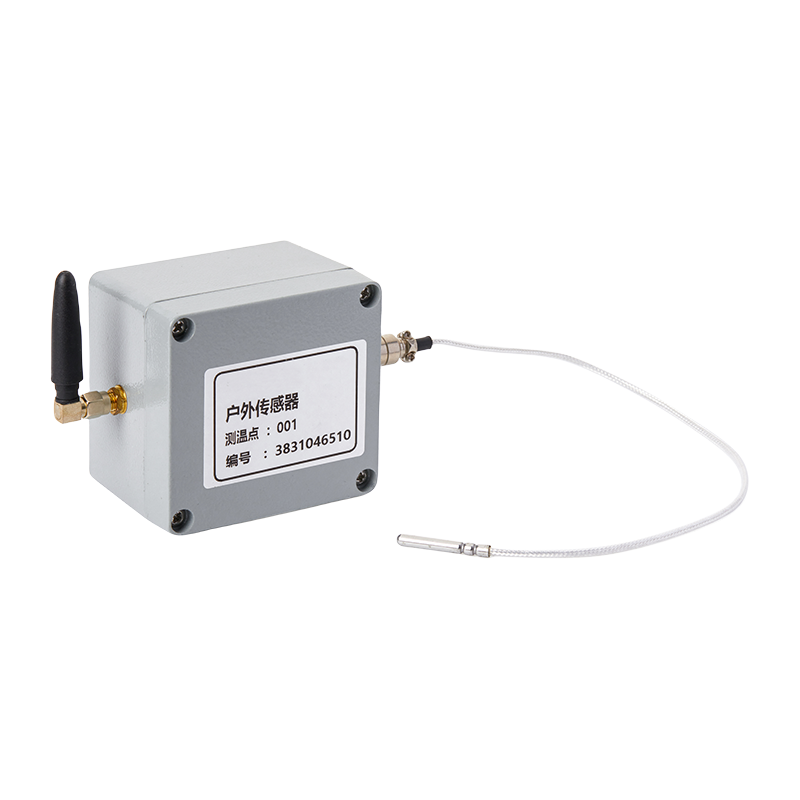
The manufacturer behind this product focuses on data sensing and intelligent connectivity for smart factories. Its product portfolio includes broadband power line carriers, wireless temperature monitoring systems, transmitters, flow meters, and automatic door controllers. This portfolio indicates an integrated understanding of industrial field devices, communication networks, and equipment data.
Sensor and Edge Hardware Capability
The use of a MEMS sensing chip demonstrates an emphasis on compact, high-sensitivity edge hardware. Edge devices are the foundation of industrial digitalization because they convert physical conditions into usable data. A flow meter that combines sensing, processing, display, and communication can provide data directly at the equipment level.
This reduces the distance between the physical process and the digital control system. It also allows manufacturers to design products that are more compatible with broader industrial IoT architectures rather than treating each meter as an isolated instrument.
Integrated Electronic Design
The product combines several functions in one enclosure: sensing, signal processing, display, analog output, digital communication, and auxiliary output. Integrating these functions requires careful circuit design, power management, electromagnetic compatibility considerations, software development, and production testing.
A DC24V/2.5W design is well matched to common industrial control cabinets and field instrumentation systems. Low power consumption can simplify power distribution and reduce heat generation in compact equipment assemblies.
Calibration and Measurement Consistency
Flow measurement products require calibration to establish the relationship between sensor response and actual gas flow. A strong manufacturing process should control reference conditions, calibration procedures, test equipment, and traceability. It should also verify zero behavior, output linearity, communication function, display operation, and alarm or pulse behavior.
The stated accuracy and repeatability are supported not only by the sensing chip but also by calibration and data-processing methods. Consistent production procedures help ensure that instruments supplied for different machines or sites behave predictably.
Mechanical Interface Standardization
Standard mechanical connections make installation easier and reduce engineering effort. The availability of BSPT internal thread and G internal thread options gives customers a choice based on regional standards, piping design, and existing equipment.
Standard interfaces can also simplify replacement. If a meter needs to be removed for inspection or service, technicians can work with familiar fittings and connection dimensions. This helps reduce downtime and lowers the risk of installation errors.
Industrial Data Integration
The manufacturer’s broader focus on industrial communication and smart-factory solutions provides an important advantage. A flow meter is more valuable when its data can be used with other information, such as equipment temperature, pressure, energy consumption, machine status, or production output.
By working across sensing and connectivity technologies, the company can support customers that need more than a single product. It can help create a connected measurement layer that links field devices with industrial control and management systems.
Application-Oriented Product Development
Industrial products should be developed around real operating environments rather than laboratory specifications alone. The AI-FK includes features that reflect practical field requirements: explosion-proof construction, robust communication, a clear display, standard outputs, flexible interfaces, and optional measurement functions.
This application-oriented approach helps bridge the gap between instrument design and factory implementation. It also gives system integrators a platform that can be adapted to different equipment, gas lines, and control architectures.
Installation and Commissioning Guidelines
Correct installation is essential for achieving reliable measurement. Before installation, users should confirm the gas type, flow range, pressure, medium temperature, ambient temperature, humidity, hazardous-area classification, connection type, power supply, and required output signals.
The piping should be clean and free from particles, oil, water, and other contaminants that could affect a sensor intended for clean gases. If the gas source may contain liquid droplets or solid particles, appropriate filtration, drying, or separation equipment should be installed upstream.
The meter should be installed according to the specified flow direction and mechanical interface requirements. Threaded connections should be tightened correctly without applying excessive force to the instrument body. Sealants should be selected for compatibility with the gas and the operating temperature and pressure.
Flow disturbances can affect measurement. Valves, elbows, reducers, regulators, and tees located close to the meter may create turbulence or an uneven velocity profile. Where possible, the installation should provide suitable straight pipe sections and avoid placing the sensor immediately downstream of a significant disturbance.
The DC24V supply should be stable and correctly wired. Signal cables should be routed away from high-power switching cables where practical. In electrically noisy environments, shielded cables, appropriate grounding, and correct separation between power and signal wiring can improve communication and analog output performance.
For RS485 networks, the installer should configure the correct device address, communication parameters, cable polarity, bus topology, and termination. Modbus RTU networks should avoid unnecessary star connections and should use appropriate termination at the ends of the main bus when required by the network design.
In hazardous areas, all wiring, barriers, glands, enclosures, and associated equipment must comply with the product’s certification requirements. Installation should be performed by personnel qualified to work with the relevant explosion-proof and intrinsically safe systems.
During commissioning, the operator should verify zero flow, display values, analog output scaling, Modbus communication, cumulative flow behavior, pulse or auxiliary output function, and alarm settings. Testing should be performed under controlled and safe conditions.
Maintenance and Long-Term Reliability
Thermal gas mass flow meters generally require less mechanical maintenance than meters with moving parts. However, reliable long-term performance still depends on suitable gas quality, correct installation, and periodic verification.
Users should inspect the piping and connections for leakage, corrosion, mechanical stress, or contamination. The display should be checked for readability, and the reported zero value should be reviewed during known no-flow conditions. Unexpected zero drift, unstable readings, or communication errors may indicate a process, wiring, or sensor issue.
Filters and dryers installed upstream should be maintained according to their service requirements. A blocked filter can reduce flow and create a misleading impression of process under-performance. Liquid contamination may also affect a sensor designed for dry or clean gas measurement.
Communication systems should be checked for loose terminals, incorrect addresses, duplicate device IDs, damaged cables, and grounding problems. A structured maintenance program can record flow trends, calibration checks, alarm events, and replacement history.
For critical applications, periodic calibration or comparison with a traceable reference instrument may be appropriate. The required interval depends on gas type, operating conditions, accuracy requirements, contamination risk, and the consequences of measurement error.
Energy Management and Industrial IoT Value
Flow measurement creates a direct connection between physical resource use and management decision-making. In a smart factory, gas consumption data can be assigned to machines, production cells, product batches, or operating shifts. This makes it possible to identify inefficient equipment and compare actual consumption with production output.
For compressed air, the meter can support leak surveys and demand profiling. For inert gases, it can help identify unnecessary purge duration or excessive standby consumption. For process gases, it can support recipe verification and quality analysis.
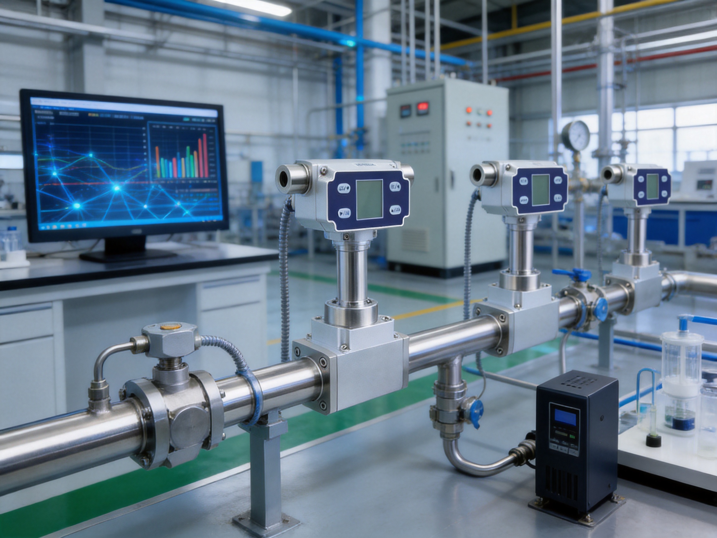
When multiple AI-FK meters are connected through RS485 or analog interfaces, the data can be collected by an edge gateway. The gateway may then transmit information to a supervisory platform or industrial database. In combination with wireless temperature monitoring, transmitters, and power line communication equipment, flow data can become part of a wider condition-monitoring and energy-management system.
This integrated approach has several benefits. Maintenance teams can prioritize equipment based on actual operating data. Production engineers can identify process deviations earlier. Energy managers can quantify savings after corrective action. Management can use verified consumption information to support sustainability goals and operational planning.
Selection Considerations
Before ordering the meter, customers should define the normal, minimum, and maximum gas flow. Selecting a range that is too large can reduce effective resolution for low-flow operation, while selecting a range that is too small may cause overload or inaccurate measurement during peak demand.
The gas composition must also be considered. Thermal measurement depends on the thermal properties of the gas. The instrument is described for clean gases, and customers should provide the gas name, composition, pressure, temperature, humidity, and expected contamination level during technical review.
Pressure and temperature conditions should be compared with the standard specifications. The default working pressure is up to 1.6 MPa, while higher ratings may be customized. The medium-temperature range is -10°C to 50°C, and the storage temperature range is -10°C to 65°C.
The required output architecture should be selected before installation. A 4–20 mA output is appropriate for many PLC and DCS systems. RS485 Modbus RTU is suitable for digital networks. A PNP, pulse, 0–5 V, or 0–10 V output may be preferred for specific controllers or equipment designs.
Finally, the hazardous-area classification must be confirmed. The relevant explosion-proof certification must match the installation location and gas environment. This information should be reviewed by the responsible safety engineer before procurement.
Why Choose an Integrated Industrial Supplier?
Purchasing a flow meter from an integrated industrial electronics supplier can provide advantages beyond the individual instrument. Customers may benefit from coordinated product selection, communication compatibility, customization support, and a more consistent approach to factory digitalization.
A supplier with experience in power line communication, wireless temperature monitoring, industrial transmitters, flow measurement, and automatic door control understands that factories contain many different types of field equipment. These devices must coexist within a larger operational environment.
Such a supplier can help customers plan how flow data should be collected, transmitted, displayed, and used. This may be especially valuable for manufacturers modernizing older plants, building new smart factories, or connecting distributed equipment across multiple production areas.
The company’s stated mission is to support efficient, reliable, and green smart factories through data sensing and intelligent connectivity. The AI-FK flow meter fits this mission by converting gas movement into actionable local and networked information.
The combination of product specialization and system awareness can also improve project communication. Customers can discuss technical specifications, communication requirements, custom outputs, and integration needs with a supplier that understands both the sensor and the industrial network surrounding it.
Recommended Use Cases
The AI-FK is well suited to applications requiring clean-gas flow monitoring, low-flow sensitivity, explosion-proof construction, and industrial connectivity. Typical use cases include compressed-air submetering, inert-gas purging, analyzer gas supply, gas cabinet monitoring, process equipment control, laboratory gas systems, equipment protection, and industrial energy management.
It is especially valuable where a local display is required alongside remote data collection. Operators can read the current and accumulated flow at the installation point, while the control system receives the same information through 4–20 mA or RS485 communication.
The meter may also be appropriate where customers want to replace conventional volumetric or differential-pressure instruments with a more compact thermal sensing solution. The final choice should be based on gas compatibility, pressure, temperature, flow range, certification, installation conditions, and required accuracy.
Frequently Asked Questions
What type of device is the AI-FK?
It is an explosion-proof thermal gas mass flow meter designed for measuring and controlling clean gases, particularly in small- and medium-flow industrial applications.
What sensing technology does it use?
The meter uses a microelectromechanical system, or MEMS, flow sensing chip. The chip measures the thermal effect of gas movement and supports high sensitivity, repeatability, and compact construction.
What is the measurement range?
The stated minimum measurable flow is 0.3 NL/min, and the maximum measurable flow is 3000 NL/min. The exact range selected for a project should match the expected normal and peak flow conditions.
What accuracy can users expect?
The stated accuracy is ±1.5% of full scale. Performance depends on correct installation, gas properties, operating conditions, calibration, and use within the specified range.
Does the meter require temperature and pressure compensation?
The product is designed for gas mass measurement without the need for temperature and pressure compensation in suitable applications. Temperature and pressure measurement functions can be customized when additional process data or advanced compensation is required.
What power supply is required?
The standard working power supply is DC24V, with rated power consumption of 2.5 W.
What communication protocol is available?
The meter provides RS485 communication using the Modbus RTU protocol. It also provides a standard 4–20 mA output and one PNP output, with other output formats available for customization.
What information is shown on the LCD?
The LCD displays instantaneous flow and cumulative flow. This allows users to inspect current gas movement and accumulated consumption locally.
What mechanical connections are available?
BSPT internal thread and G internal thread options are available. The appropriate connection should be selected according to the piping system and project requirements.
Can the meter be used in a hazardous area?
The product is described as having intrinsically safe explosion-proof certification. Before installation, users must verify the exact certification details and confirm that they match the hazardous-area classification and local safety requirements.
What is the default pressure rating?
The default working pressure is up to 1.6 MPa. Higher-pressure configurations and integrated pressure measurement and display may be available as customized options.
What gas can be measured?
The instrument is designed for clean gases. The gas type and composition should be reviewed before purchase because thermal measurement performance depends on gas properties. Special applications should be evaluated with the supplier.
What is the response time?
The specified response time is 50–1000 ms. The required response should be considered when the meter is used for control loops, alarms, switching, or rapidly changing flow conditions.
How does the meter compare with an orifice flow meter?
The thermal design can provide high sensitivity at low flow, reduce the need for a large mechanical restriction, and simplify compensation in suitable applications. An orifice system may still be preferable for certain high-temperature, high-pressure, or heavily standardized process installations.
How can the meter support energy savings?
It can measure gas consumption at equipment, branch, or production-line level. This data can help identify leakage, excessive use, abnormal operating conditions, and opportunities for process optimization.
Can the product be integrated into an industrial IoT system?
Yes. The 4–20 mA and RS485 Modbus RTU interfaces allow connection to PLCs, gateways, industrial computers, data platforms, and energy-management systems. The meter can therefore act as an edge-level source of gas-consumption data.
What should be checked before ordering?
Customers should provide the gas type, flow range, pressure, temperature, humidity, required accuracy, hazardous-area classification, mechanical connection, power supply, communication method, and any need for customized temperature, pressure, or output functions.
Conclusion
The AI-FK explosion-proof thermal gas mass flow meter provides a practical combination of sensitive MEMS-based measurement, industrial safety, flexible communication, local visualization, and customization capability. Its range from 0.3 NL/min to 3000 NL/min allows it to serve diverse clean-gas applications, while its 4–20 mA, RS485 Modbus RTU, PNP, pulse, and voltage-output options support integration with modern automation systems.
Its main advantages over many conventional alternatives include high low-flow sensitivity, stable zero performance, reduced measurement complexity, low power consumption, compact industrial construction, and the ability to operate as part of a connected factory architecture. Intrinsically safe explosion-proof certification further expands its suitability for hazardous industrial environments when correctly applied.
The product also reflects the strengths of a manufacturer focused on intelligent connectivity and industrial data sensing. By combining flow measurement with expertise in transmitters, wireless monitoring, power line communication, and smart-factory integration, the company can support customers seeking both a reliable field instrument and a foundation for broader industrial digitalization.
For factories working to improve safety, energy efficiency, process consistency, and operational visibility, the AI-FK offers a strong platform for gas-flow monitoring. Proper selection, installation, certification review, calibration, and maintenance will help ensure that the instrument delivers dependable performance throughout its service life.
References
1. Product technical information for the AI-FK explosion-proof thermal gas mass flow meter.
2. Industrial measurement engineering principles for thermal mass gas flow sensing.
3. General practices for 4–20 mA industrial instrumentation and analog signal transmission.
4. Modbus RTU communication principles for RS485 industrial networks.
5. General safety principles for intrinsically safe electrical equipment in hazardous areas.
6. Industrial energy-management practices for compressed-air and process-gas monitoring.
7. MEMS sensor design and manufacturing principles for industrial measurement applications.
8. Smart-factory and industrial IoT architecture principles for edge-level data acquisition.