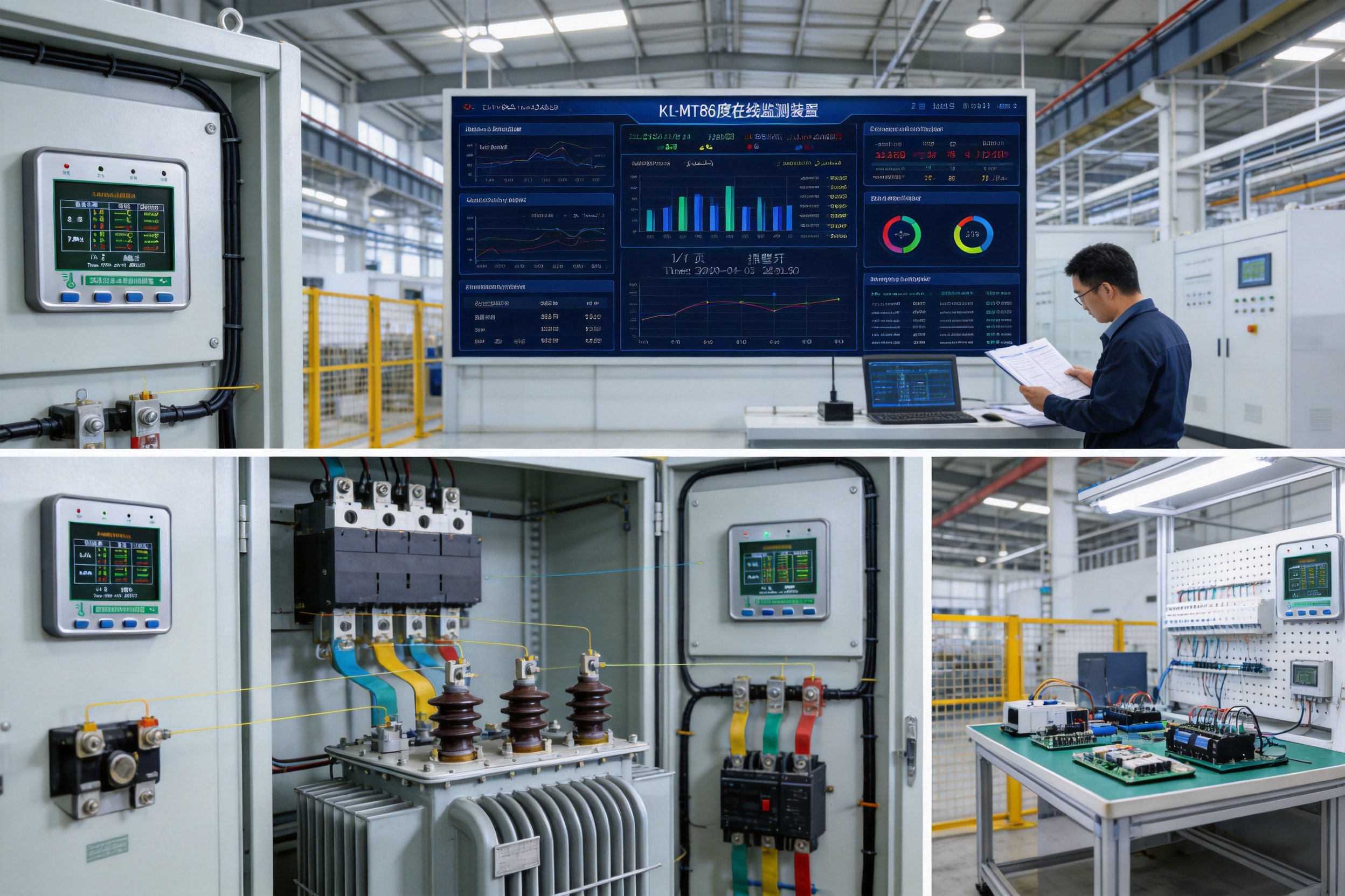


Introduction
Temperature is one of the clearest early indicators of abnormal operation in electrical equipment. Loose connections, overloaded conductors, aging insulation, poor contact pressure, oxidation, and uneven phase loading can all generate excessive heat before a visible failure occurs. In high-voltage environments, however, measuring temperature continuously is not simple. The monitoring point may be surrounded by strong electromagnetic fields, high current, restricted installation space, and insulation requirements that make conventional wired measurement difficult.
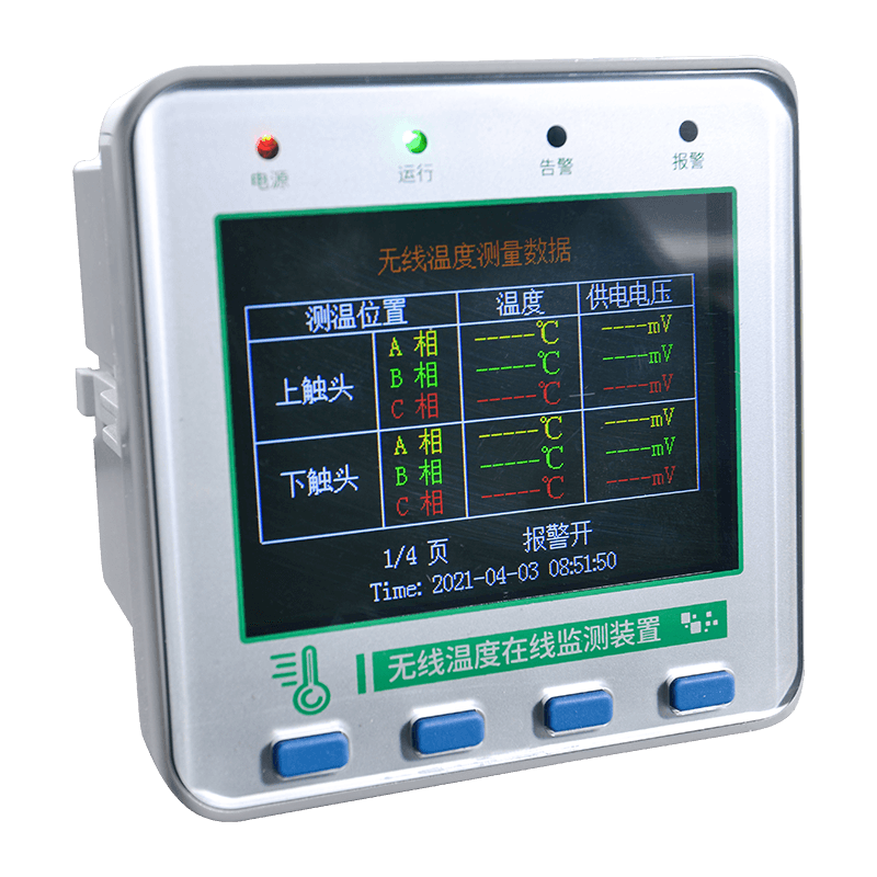
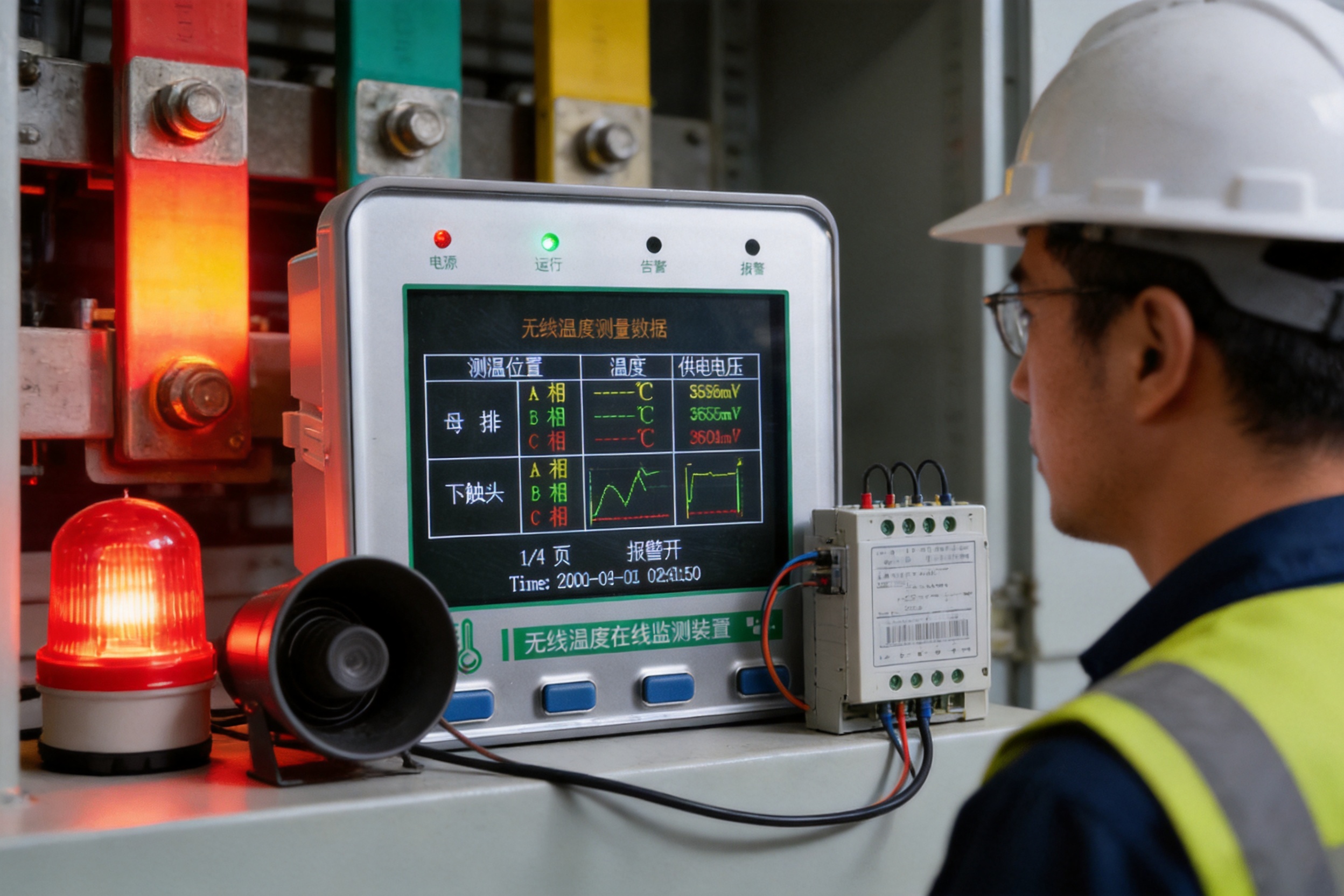
The KL-MT86MP small color screen wireless temperature measurement host is designed to address these challenges. It receives temperature data from wireless sensors installed directly on high-voltage electrical contacts and presents the information on a standard 86 × 86 color display. It can also provide alarm output, historical records, RS485 communication, Modbus connectivity, and network operation for centralized equipment management.
Instead of relying on a long wired connection from every measurement point, the system uses wireless communication between sensors and the host. This architecture reduces wiring complexity, helps maintain electrical isolation, and makes it easier to monitor locations that are difficult or unsafe to access during normal operation. The host is suitable for industrial production equipment, high-power motors, high-voltage switches, busbar joints, outdoor disconnectors, transformers, and other electrical contacts where temperature can rise rapidly.
For operators, the value of the KL-MT86MP is not limited to displaying a live temperature. It combines local visualization, sensor management, alarm functions, data records, password-controlled settings, and industrial communication in one embedded device. This combination supports both on-site inspection and integration with a larger automation, energy-management, or smart-grid platform.
Small Color Screen Wireless Temperature Measurement Host
Why Wireless Temperature Monitoring Matters
The limitations of conventional inspection
Many electrical facilities still depend on periodic manual inspection or handheld infrared measurement. These methods can be useful, but they only provide a temperature snapshot at the moment of inspection. A connection that overheats between inspection rounds may cool down before an operator arrives, leaving no evidence of the problem. Manual inspection can also be affected by access restrictions, equipment shutdown requirements, line-of-sight limitations, and human error.
Permanent wired sensors can provide continuous measurement, but wiring high-voltage contacts introduces additional engineering requirements. Cables must be routed through cabinets and insulation structures, protected against mechanical damage, and kept away from electromagnetic interference. In crowded switchgear or compact electrical panels, there may not be enough space for conventional cable routing. A wireless sensor installed directly at the measurement point can reduce these challenges.
Direct measurement at critical contacts
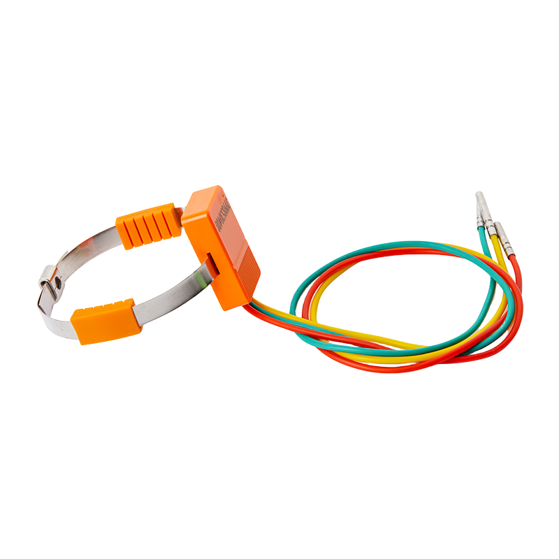
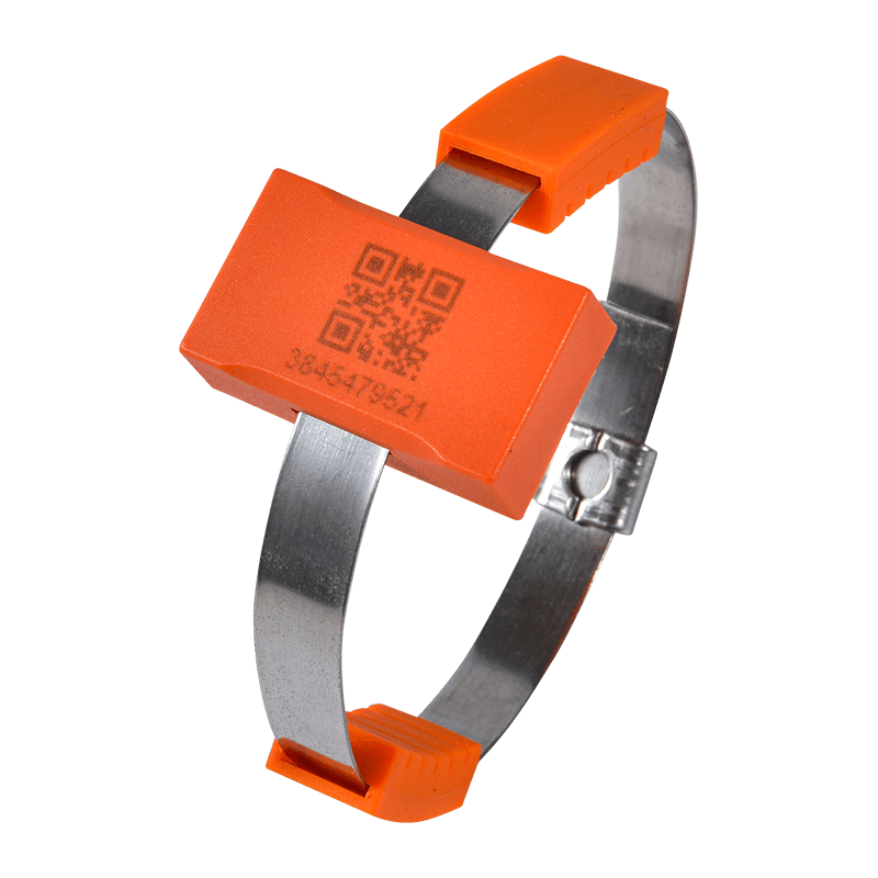
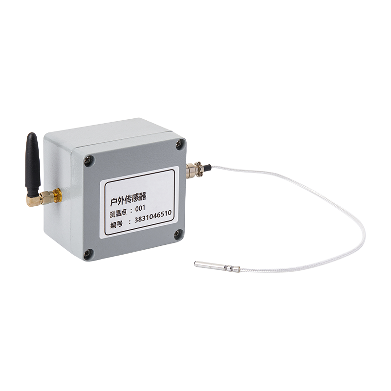
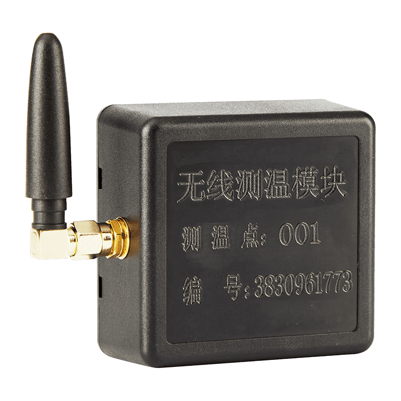
The wireless sensor is installed at the point where heat is most likely to develop. This may include a busbar joint, a switch contact, a cable connection, a transformer connection, or another high-current interface. Because the sensor is placed close to the thermal source, the monitoring system can identify abnormal temperature changes without depending on indirect measurements from a more distant location.
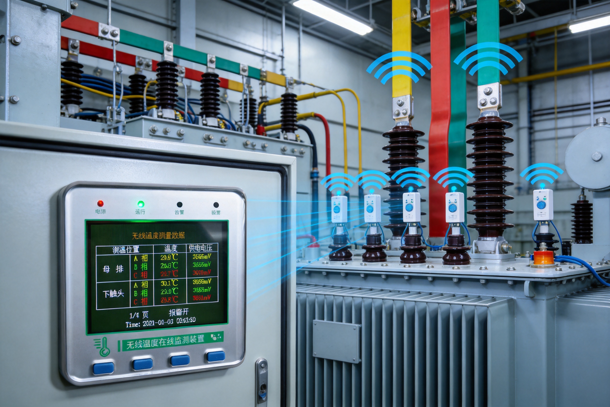
The sensor transmits measured temperature and sensor operating voltage to the receiving host. The host then displays the information and evaluates it against configured alarm parameters. This creates a continuous monitoring path from the physical connection to the operator interface and, when required, to a supervisory control or data-acquisition system through RS485 communication.
Suitable for difficult electrical environments
High-voltage installations can combine strong electric fields, strong magnetic fields, high temperatures, vibration, dust, and limited working space. A temperature monitoring solution must therefore do more than measure accurately under normal laboratory conditions. It must also support safe installation, dependable wireless data transmission, clear local indications, and reliable event storage.
The system architecture separates the measurement point from the display and control point. Sensors can be installed on electrical equipment, while the KL-MT86MP host is embedded in a suitable control-panel position. This separation helps operators obtain data without opening energized equipment or approaching high-risk contacts for every inspection.
Product Architecture and Operating Principle
The KL-MT86MP functions as the central host of a wireless temperature monitoring system. Wireless sensors collect data at selected high-voltage equipment points. The sensors send their readings through the selected radio channel to the host. The host receives, processes, displays, stores, and communicates the information.
The wireless frequency can be selected as either 2.4 GHz or 433 MHz, depending on the system configuration and application requirements. Providing two frequency options gives engineering teams greater flexibility when considering cabinet structure, installation environment, transmission conditions, and compatibility with the planned monitoring network.
A single host can manage up to 240 wireless sensors. This capacity allows one display host to supervise multiple phases, multiple cabinets, or multiple pieces of electrical equipment. In larger facilities, up to 128 hosts can be connected through the communication network, allowing the monitoring system to be expanded across substations, production lines, distribution rooms, and other operational areas.
The host includes an RS485 communication interface with a communication distance of up to 1,200 meters without a repeater, subject to installation conditions and the quality of the communication cable. Modbus communication supports connection with industrial control systems, monitoring software, energy-management platforms, and other equipment capable of communicating with the wireless temperature measurement system protocol.
The device accepts AC 85–265 V or DC 110–370 V, which makes it suitable for a broad range of industrial control-panel power arrangements. Its overall power consumption is no more than 5 VA. This low consumption is useful in applications where many monitoring devices are installed in a distributed control system and where panel power capacity must be managed carefully.
| Item | Specification | Application significance |
|---|---|---|
| Display format | Standard 86 × 86 color screen | Clear local visualization in an embedded panel installation |
| Wireless frequency | 2.4 GHz or 433 MHz, optional | Allows configuration according to the application environment |
| Wireless sensor capacity | Up to 240 sensors | Supports multi-point monitoring across equipment and phases |
| Communication interface | RS485 | Enables connection to industrial automation and supervisory systems |
| Communication distance | Up to 1,200 m without repeater | Supports distributed installation over a large industrial area |
| Network capacity | Up to 128 hosts | Allows system expansion across multiple rooms or facilities |
| Communication protocol | Modbus protocol for wireless temperature measurement systems | Facilitates data exchange with compatible control software |
| Power supply | AC 85–265 V or DC 110–370 V | Compatible with common industrial control power sources |
| Power consumption | ≤5 VA | Reduces the host’s impact on panel energy consumption |
| Installation | Embedded installation | Fits compact control-panel and switchgear layouts |
Small Color Screen Design
The standard 86 × 86 color screen is one of the most practical features of the host. It provides a compact interface while retaining enough visual space to present temperature readings, sensor information, alarm status, clock data, and configuration menus. This format is appropriate for control panels where installation space is limited but a local display is still required.
Color presentation improves the distinction between normal values, warning conditions, alarm conditions, and system information. Operators can identify changes more quickly than they might with a basic monochrome indicator or a collection of separate lamps. The backlight switch is controllable, allowing the display behavior to be adapted to different locations, operating schedules, and energy-management preferences.
A local display is especially valuable during commissioning and maintenance. Technicians can verify sensor communication, inspect the values of individual monitoring points, confirm alarm thresholds, and review records without immediately connecting a laptop or accessing a central server. This can shorten troubleshooting time and reduce dependence on a remote monitoring station.
Compact installation with practical visibility
The embedded design allows the host to be integrated into a panel door or another suitable control enclosure. A compact panel-mounted host keeps the monitoring interface close to the equipment being supervised. It also avoids the need for a separate large industrial computer when the application requires only local display and basic network communication.
The display is not intended to replace a complete supervisory platform in a large facility. Instead, it provides an effective local operating layer that can function independently or work together with host computer software and higher-level systems. This layered approach is useful because operators can respond locally while maintenance teams and managers access historical data centrally.
Comprehensive Monitoring Functions
Receiving sensor data
The host receives the temperature measured by each wireless sensor and also receives the sensor operating voltage. Monitoring sensor voltage provides an additional view of sensor condition. If the voltage changes abnormally, maintenance personnel may investigate battery status, sensor aging, connection quality, or environmental effects before the sensor stops reporting completely.
Real-time display
Received values are shown in color for intuitive interpretation. The display can present the operating temperature of the monitored points and indicate whether a value is approaching or exceeding a configured threshold. This supports rapid local decision-making, especially in electrical rooms where an operator needs to identify a potentially overheated phase or connection quickly.
Real-time clock and event timing
The built-in real-time clock provides the time reference for event logging. Time information is essential when reviewing an alarm, comparing temperature changes with production activity, or determining how long a high-temperature condition lasted. It also helps maintenance teams correlate thermal events with switching operations, load changes, environmental conditions, and previous service work.
Flexible parameter settings
All parameters can be adjusted through the host interface. This flexibility is important because different equipment types may have different normal operating temperatures and different alarm requirements. Settings can be adapted to the characteristics of a motor, switchgear assembly, transformer, busbar connection, or other monitored object.
Configuration data is retained when power is removed, reducing the risk of losing settings during maintenance or a power interruption. Password protection is used when parameters are changed. The system supports both a user password and a system password, with the system password providing access to more advanced settings. This separation helps prevent unauthorized or accidental changes to important monitoring parameters.
Alarm relay and buzzer
When an alarm event occurs, the host activates a buzzer and provides a relay dry-contact output. The dry contact can be connected to an external warning lamp, control circuit, annunciator, automation input, or shutdown logic, provided that the connected circuit is designed within the relay rating.
The relay specification is AC 220 V/5 A, with one set of passive normally open and normally closed contacts. A passive dry contact gives system integrators flexibility because the external control circuit can provide the required sensing voltage. It can also simplify integration with existing alarm panels and industrial control equipment.
Extreme-temperature records
The host records the highest and lowest temperatures at each measurement point on a monthly basis. The corresponding sensor operating voltage and the time of occurrence are recorded with the extreme temperature data. This information is useful for identifying seasonal patterns, examining the influence of production cycles, and determining whether a connection is gradually becoming warmer over time.
When the system is used across multiple years, it automatically overwrites the data for the same month from the previous year. This creates a rolling annual record structure. It allows the host to preserve current monthly comparative information without requiring unlimited internal storage.
Temperature alarm records
For each temperature alarm, the host records the temperature, start time, and end time of each alarm phase at the relevant measurement location. Up to 100 alarm records can be saved. When the number exceeds 100, the oldest record is automatically overwritten.
This event history helps maintenance personnel move beyond a simple present-value inspection. They can review whether alarms are isolated incidents, recurring events, short-duration peaks, or long-lasting conditions. The duration of an alarm can be particularly important because a brief transient and a persistent overheating problem may require different responses.
Temperature imbalance records
In three-phase systems, unequal temperatures can indicate an unbalanced load, a weak connection, a phase-specific contact problem, or an equipment condition that does not affect all phases equally. The host records the temperature and occurrence time of each phase at the same monitoring location when the phase temperatures are not equal.
The system calculates the degree of imbalance and stores the information monthly. As with the extreme-temperature records, the previous year’s data for the same month is automatically overwritten when the system operates across years. This function provides an additional diagnostic dimension beyond the absolute high-temperature alarm.
Default Alarm Parameters and Configuration Flexibility
The supplied technical information identifies default temperature alarm settings that include an upper limit of +90°C and a lower limit of −20°C. It also lists another temperature alarm setting with an upper limit of +60°C and a lower limit of −10°C, together with an alarm voltage value of 2700 mV. These values should be understood as configurable defaults or application parameters rather than universal limits for every type of equipment.
Actual alarm thresholds should be selected by qualified engineers according to the insulation system, conductor material, contact design, ambient temperature, rated load, installation method, manufacturer recommendations, and applicable safety standards. A threshold that is appropriate for one electrical assembly may be unsuitable for another. The host’s adjustable parameter structure allows the monitoring system to be aligned with those engineering decisions.
Configurable alarm values also support staged maintenance strategies. A lower warning threshold can be used to draw attention to a developing trend, while a higher threshold can trigger a more urgent response. External control actions should be designed carefully so that the relay output is used appropriately and does not create an unsafe or unintended equipment response.
Advantages Compared with Conventional and Competing Approaches
Compared with manual infrared inspection
The principal advantage over periodic infrared inspection is continuity. A handheld camera captures conditions during a scheduled visit, whereas a wireless monitoring system can observe conditions throughout operation. Continuous data improves the chance of identifying overheating during peak load, nighttime operation, unattended periods, or other times when personnel are not present.
The system also records the timing and duration of events. Manual inspection usually requires a separate documentation process and may not capture the exact moment when a temperature exceeded a safe operating range. With automated records, operators can review the event history and investigate the cause more systematically.
Compared with fully wired temperature systems
Wireless sensors can reduce the quantity of signal wiring required inside high-voltage equipment. This can simplify installation, reduce routing work, and make retrofitting more practical. Wireless architecture is particularly useful where sensors must be placed on moving, rotating, insulated, or spatially restricted components, or where new cables would require significant cabinet modification.
The wireless approach also helps separate the sensor from the receiving host electrically. This can support insulation planning and reduce the complexity associated with bringing conductors from high-voltage points to a low-voltage display device. Proper installation and compliance with the equipment’s insulation and safety requirements remain essential, but the architecture offers a practical alternative to extensive wiring.
Compared with basic wireless monitors
Some basic wireless temperature products provide only a live reading. The KL-MT86MP adds a broader operating and maintenance feature set: color display, controllable backlight, real-time clock, relay alarm, buzzer, sensor-voltage reporting, monthly extreme records, alarm history, temperature imbalance records, password management, RS485, and Modbus communication.
This combination reduces the need to combine several separate devices. A stand-alone indicator may not retain event history. A data logger may not provide a local alarm relay. A wireless receiver may not offer phase imbalance analysis. By bringing these capabilities into one host, the system can reduce integration complexity and give operators a more complete view of equipment condition.
Compared with isolated single-point solutions
The ability to manage up to 240 wireless sensors allows the host to support a coordinated monitoring strategy. Instead of treating each contact as an independent instrument, the system can organize multiple measurement points within one network. This is valuable for three-phase comparison, cabinet-to-cabinet analysis, and expansion as additional equipment is brought under monitoring.
The network capacity of up to 128 hosts further supports distributed deployment. A facility can use local hosts for individual electrical rooms or production areas while communicating through RS485 with a centralized system. This scalable structure is more suitable for industrial growth than a product designed only for one local sensor or one isolated cabinet.
Industrial Communication and Smart-Facility Integration
Industrial temperature monitoring is most valuable when its data can be used by other systems. The KL-MT86MP provides RS485 communication and supports the Modbus protocol used for wireless temperature measurement systems. This enables temperature data and alarm states to be exchanged with compatible programmable controllers, supervisory systems, industrial computers, energy-management platforms, and facility monitoring software.
Communication integration can support several operating scenarios. A control room may display temperature values from many electrical rooms. A maintenance platform may create work orders when a temperature alarm persists. An energy-management system may compare thermal behavior with current demand. A production system may associate an electrical equipment alarm with a process interruption or a change in operating schedule.
The host can also serve as an edge-layer device. It collects data close to the equipment, performs initial alarm evaluation and record management, and then communicates relevant information to a higher-level platform. This reduces dependence on a remote server for immediate local action. Even if the central software is temporarily unavailable, the local display, buzzer, relay, and internal records can continue to support on-site operation.
Engineering and Manufacturing Strengths
Self-developed industrial hardware
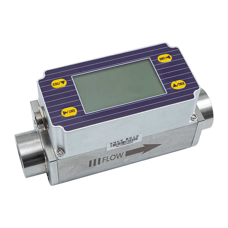
The manufacturer is a high-tech enterprise focused on smart-factory development, data sensing, and intelligent connectivity. Its product scope includes broadband power line carriers, wireless temperature monitoring systems, transmitters, flow meters, and automatic door controllers. This product portfolio indicates experience across sensing, communication, industrial measurement, and control interfaces.
For the KL-MT86MP, that combination of capabilities is important. A reliable monitoring host is not simply a screen. It must coordinate wireless data reception, sensor management, alarm logic, data storage, communication protocols, power conversion, display operation, and installation requirements. Experience with multiple industrial product categories can support a more integrated approach to product engineering.
From sensing to data integration
The company’s stated focus on data sensing and intelligent connectivity aligns directly with the needs of wireless temperature monitoring. Sensors generate field data, the host organizes and evaluates it, and industrial communication makes the data useful to other systems. This end-to-end perspective can help reduce compatibility gaps between field devices and software platforms.
The company also develops industrial data integration solutions for equipment condition monitoring, refined energy management, and production-process optimization. The KL-MT86MP can therefore be considered part of a wider industrial digitalization strategy rather than an isolated display instrument. Its temperature data can contribute to preventive maintenance and broader equipment-performance analysis.
Manufacturing process considerations
A product used in high-voltage equipment monitoring requires disciplined manufacturing at each stage. Electronic component selection must be aligned with the specified operating voltage, environmental range, power consumption, and communication functions. Printed circuit board assembly must maintain consistent solder quality and dependable connections. The display, interface components, wireless module, power supply section, relay output, and communication interface must work together as a stable industrial product.
Production quality is also influenced by process control. Incoming materials should be checked against defined specifications. Assembly procedures should control component placement, soldering, wiring, and mechanical fit. Functional testing should verify power input, display behavior, communication, wireless reception, alarm activation, relay operation, parameter retention, and clock performance. Final inspection should confirm labeling, enclosure condition, terminal integrity, and installation suitability.
Because the device may operate continuously in industrial panels, manufacturing consistency is as important as the feature list. Repeatable assembly, traceable testing, and systematic quality management help ensure that units perform consistently when deployed across multiple cabinets or sites. These processes are especially valuable for projects that require many hosts and sensors to be commissioned as one coordinated system.
Application-oriented product development
The product’s specifications reflect practical field requirements: a compact 86 × 86 format, embedded installation, broad power input, low consumption, controllable backlight, long RS485 communication distance, multiple wireless frequency options, and support for a large number of sensors. These features suggest development based on real industrial installation conditions rather than on laboratory measurement alone.
Application-oriented development also appears in the record functions. Monthly high and low temperature storage, alarm event history, sensor voltage monitoring, and temperature imbalance analysis address the questions that maintenance teams commonly ask: When did the problem start? Which phase was affected? Was the condition temporary or persistent? Did sensor voltage change? Has the same month shown abnormal behavior before?
Reliability, Security, and Environmental Performance
The wireless temperature monitoring system is designed for real-time operation in demanding electrical environments. Its reliability depends on the complete system, including correct sensor installation, appropriate frequency selection, suitable host placement, proper power supply, communication configuration, and regular maintenance. The KL-MT86MP contributes through local event handling, data retention, alarm outputs, and industrial communication.
The specified operating temperature range is −10°C to +70°C. The specified operating humidity is no more than 90% RH, non-condensing and non-corrosive. These conditions cover many indoor industrial control environments, although the actual enclosure and installation location must be selected to prevent condensation, corrosive exposure, excessive heat, or other conditions outside the specification.
The specified altitude is up to 2,500 meters. The protection level is IP20, which indicates that the host is intended for installation inside a suitable cabinet or protected control-panel environment rather than direct exposure to water, dust, or outdoor weather. The insulation resistance is specified as at least 100 MΩ under the stated test conditions of 10–30°C and relative humidity below 80%.
Password management provides a basic operational security layer. Requiring a password for parameter changes helps protect alarm thresholds, communication settings, and other configuration items from unauthorized adjustment. The distinction between user and system passwords can help separate routine access from advanced engineering functions.
As with all industrial monitoring products, cybersecurity at the full system level should include cabinet access control, network segmentation where applicable, controlled software access, documented configuration changes, and regular maintenance procedures. Password protection is one component of responsible system operation, not a replacement for an overall security policy.
Applications Across Industrial Electrical Systems
High-voltage switchgear
Switchgear contains numerous contacts and joints where resistance can increase because of aging, vibration, contamination, or insufficient tightening. Wireless sensors can be installed at selected high-risk points, while the host displays the temperature status locally. Alarm relay output can be connected to the switchgear room annunciation system or a central monitoring panel.
Busbar joints and cable connections
Busbar connections carry high current and may experience localized heating if contact resistance increases. Because a thermal problem can be concentrated at one joint, direct measurement is more informative than relying only on room temperature or cabinet temperature. The host’s extreme-temperature and imbalance records can assist with identifying recurring or phase-specific behavior.
Transformers and distribution equipment
Transformers and distribution assemblies often operate continuously and may be difficult to inspect while energized. Monitoring contact temperatures and related points can provide an additional condition indicator. Operators can compare alarm history with loading patterns and maintenance activity to determine whether further inspection is necessary.
High-power motors
High-power motors can develop connection or terminal problems that produce local heating. Wireless temperature monitoring can help observe these points without adding extensive wiring around the motor installation. The system can be used alongside current, vibration, insulation, and other condition-monitoring methods.
Outdoor disconnectors and exposed electrical contacts
Outdoor disconnectors and related equipment may face changing ambient temperatures, wind, humidity, and weather exposure. The host itself should be installed in an appropriately protected panel, while the sensor installation must be designed for the equipment environment. Temperature records can help maintenance teams distinguish normal environmental variation from abnormal contact heating.
Implementation Recommendations
Survey the equipment before installation
Before deployment, engineers should identify the points most likely to develop abnormal heat. These may include high-current joints, frequently operated contacts, connections with a history of maintenance issues, and locations that are difficult to inspect manually. The number and arrangement of sensors should reflect the electrical design and the desired diagnostic coverage.
Plan wireless coverage
Wireless performance depends on host location, cabinet materials, equipment arrangement, electromagnetic conditions, and the selected frequency. A site survey should verify that sensors can communicate reliably with the host in the actual operating environment. Where the facility includes multiple rooms or large distances, the network plan should consider the RS485 topology, cable routing, host addresses, and any required repeaters or communication infrastructure.
Set alarm values responsibly
Alarm values should be established using equipment-specific engineering data. Operators should define the meaning of warning, alarm, and emergency actions before commissioning the system. If the relay output is connected to an external control circuit, the response should be reviewed carefully to prevent nuisance trips or unsafe automatic actions.
Commission and document the system
Commissioning should include sensor identification, temperature plausibility checks, operating-voltage verification, wireless communication tests, display checks, alarm simulation, relay verification, clock setting, password assignment, and RS485 communication testing. Each sensor should be documented by equipment location, phase, measurement point, and identification number.
Documentation should also include the selected wireless frequency, communication baud rate, host address, Modbus settings, alarm parameters, relay wiring, installation date, and responsible maintenance personnel. Clear records make future troubleshooting and expansion more efficient.
Use records for preventive maintenance
Historical data should be reviewed regularly rather than only after an alarm occurs. Monthly extreme temperatures can reveal gradual changes. Alarm duration can identify intermittent or persistent faults. Temperature imbalance can indicate phase-specific issues. Sensor voltage history can help identify a sensor that may require service.
By combining these records with load data, switching schedules, inspection reports, and maintenance history, organizations can move toward condition-based maintenance. This approach can reduce unnecessary shutdowns while increasing the probability that a developing thermal fault is addressed before it causes equipment damage.
Maintenance and Lifecycle Value
The low power consumption and embedded format make the KL-MT86MP suitable for continuous operation in industrial panels. Its broad input range can simplify replacement planning when different control cabinets use different power systems. The display and local alarm functions reduce the need for a separate indicator, while RS485 and Modbus support future integration with centralized software.
The system’s expandable sensor capacity also supports phased investment. An organization can begin by monitoring the most critical equipment and later add sensors or hosts as risk assessments evolve. This is often more practical than replacing an entire monitoring architecture when a facility expands.
Lifecycle value also comes from the information generated by the system. A temperature monitor that only shows a current value may help with immediate observation but provides limited evidence for long-term maintenance planning. The KL-MT86MP’s event and monthly records create a more useful operational history, helping organizations identify recurring patterns and prioritize technical resources.
For industrial users, the total value of a monitoring product includes installation effort, integration effort, operator training, maintenance workload, and data usefulness. The combination of wireless field sensing, compact local display, alarm output, records, and industrial communication can reduce the number of separate components needed to achieve a complete monitoring function.
Technical Specification Summary
| Category | Technical specification |
|---|---|
| Model | KL-MT86MP |
| Product type | Small color screen wireless temperature measurement host |
| Wireless frequency | 2.4 GHz or 433 MHz optional |
| Managed wireless sensors | Up to 240 |
| Communication interface | RS485 |
| Communication distance | Up to 1,200 m without repeater |
| Networked hosts | Up to 128 |
| Protocol | Modbus protocol for wireless temperature measurement systems |
| Baud rates | 1,200, 2,400, 4,800, 9,600, and 19,200 bps |
| Relay output | AC 220 V/5 A; one set of passive normally open/normally closed contacts |
| Operating voltage | AC 85–265 V / DC 110–370 V |
| Power consumption | ≤5 VA |
| Operating temperature | −10°C to +70°C |
| Operating humidity | ≤90% RH, non-condensing and non-corrosive |
| Altitude | ≤2,500 m |
| Protection level | IP20 |
| Insulation resistance | ≥100 MΩ under specified test conditions |
| Installation method | Embedded installation |
Frequently Asked Questions
What does the wireless host monitor?
The host receives temperature data and sensor operating voltage from wireless temperature sensors installed at selected electrical equipment points. It displays the information, evaluates alarm conditions, stores records, and can transmit data through RS485.
How many wireless sensors can one host manage?
One KL-MT86MP host can manage up to 240 wireless sensors. The actual number used in a project should be determined by the equipment layout, wireless coverage, required measurement points, and system configuration.
Which wireless frequencies are available?
The wireless frequency can be configured as 2.4 GHz or 433 MHz. The appropriate choice depends on the installation environment, equipment structure, communication requirements, and project design.
Can the host connect to a supervisory system?
Yes. The host provides an RS485 communication interface and supports the Modbus protocol for wireless temperature measurement systems. It can therefore be connected to compatible industrial computers, controllers, supervisory software, and data-management platforms.
Does the host provide a local alarm?
Yes. When an alarm event occurs, the host can activate a buzzer and provide a relay dry-contact output. The relay has one set of passive normally open and normally closed contacts and is rated at AC 220 V/5 A.
Does the device store historical temperature information?
Yes. It records monthly highest and lowest temperatures at each measurement point, including the corresponding sensor operating voltage and occurrence time. It also stores temperature alarm records and temperature imbalance records.
How many alarm records can be stored?
Up to 100 temperature alarm records can be saved. When more than 100 records are generated, the oldest record is automatically overwritten.
What is the purpose of temperature imbalance records?
Temperature imbalance records help identify unequal temperatures among three phases at the same measurement location. The host records the temperature and occurrence time of each phase and calculates the imbalance degree.
Yes. A password is required when setting parameters. The system provides a user password and a system password, with the system password allowing access to more advanced settings.
What power supply does the host require?
The operating voltage is AC 85–265 V or DC 110–370 V. Overall power consumption is no more than 5 VA.
Where should the host be installed?
The host is designed for embedded installation, normally within a suitable industrial control panel or protected enclosure. Its IP20 protection level means it should not be exposed directly to water, outdoor weather, or uncontrolled dust.
What operating environment is specified?
The specified operating temperature is −10°C to +70°C, and the specified humidity is no more than 90% RH under non-condensing and non-corrosive conditions. The specified operating altitude is up to 2,500 meters.
Can the host replace all other electrical condition-monitoring systems?
No. It is a temperature monitoring host and should be used as part of an appropriate electrical safety and maintenance program. It can complement current, voltage, vibration, insulation, protection, and other condition-monitoring systems.
Why is local display useful if the system is connected to software?
The local display allows technicians and operators to inspect values, alarms, and settings at the equipment location. It provides immediate visibility during commissioning and maintenance and can continue to support local response even when a remote supervisory platform is unavailable.
Conclusion
The KL-MT86MP small color screen wireless temperature measurement host provides a practical way to monitor thermal conditions at high-voltage electrical equipment. Its wireless architecture helps address the difficulties of wiring high-voltage contacts, while the compact 86 × 86 color screen provides clear local visualization in a panel-mounted format.
Its main strengths include support for up to 240 wireless sensors, optional 2.4 GHz or 433 MHz communication, RS485 and Modbus integration, a communication distance of up to 1,200 meters without a repeater, relay and buzzer alarms, configurable parameters, password management, sensor-voltage monitoring, and several forms of historical record storage. These functions give the product broader operational value than a basic temperature indicator or a stand-alone wireless receiver.
The manufacturer’s focus on smart factories, data sensing, intelligent connectivity, industrial hardware, and data integration supports the product’s role in modern condition-monitoring systems. Through disciplined component selection, assembly control, functional testing, and application-oriented development, the company can provide a foundation for dependable deployment across industrial electrical installations.
When correctly engineered and installed, the system can help organizations identify overheating earlier, improve preventive maintenance, reduce dependence on periodic manual inspection, and connect field temperature data with broader industrial management platforms. For facilities seeking a compact, expandable, and communication-ready wireless temperature monitoring solution, this host offers a balanced combination of local visibility, network capability, alarm handling, and historical analysis.
References
1. Product technical information for the KL-MT86MP small color screen wireless temperature measurement host.
2. Industrial wireless temperature monitoring system application data supplied for high-voltage electrical equipment.
3. Technical specifications for RS485 communication and Modbus-based industrial monitoring systems.
4. Manufacturer information concerning smart-factory development, industrial data sensing, intelligent connectivity, and equipment condition monitoring.
5. General engineering principles for preventive maintenance and thermal monitoring of high-voltage switchgear, busbar joints, transformers, motors, and electrical contacts.