

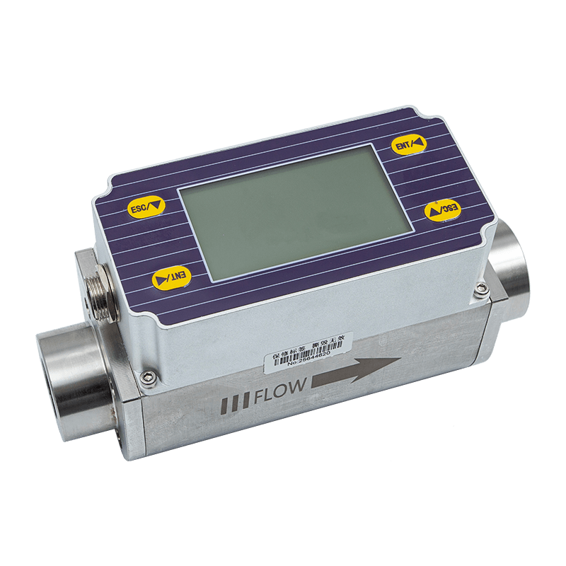
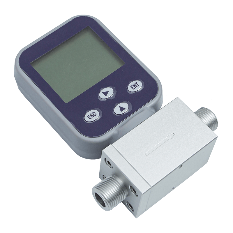
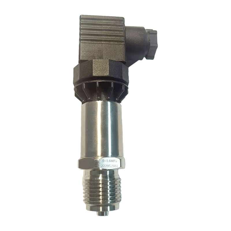
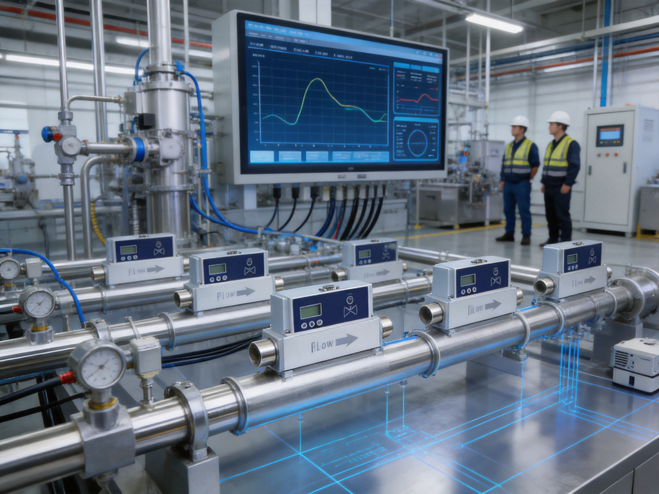
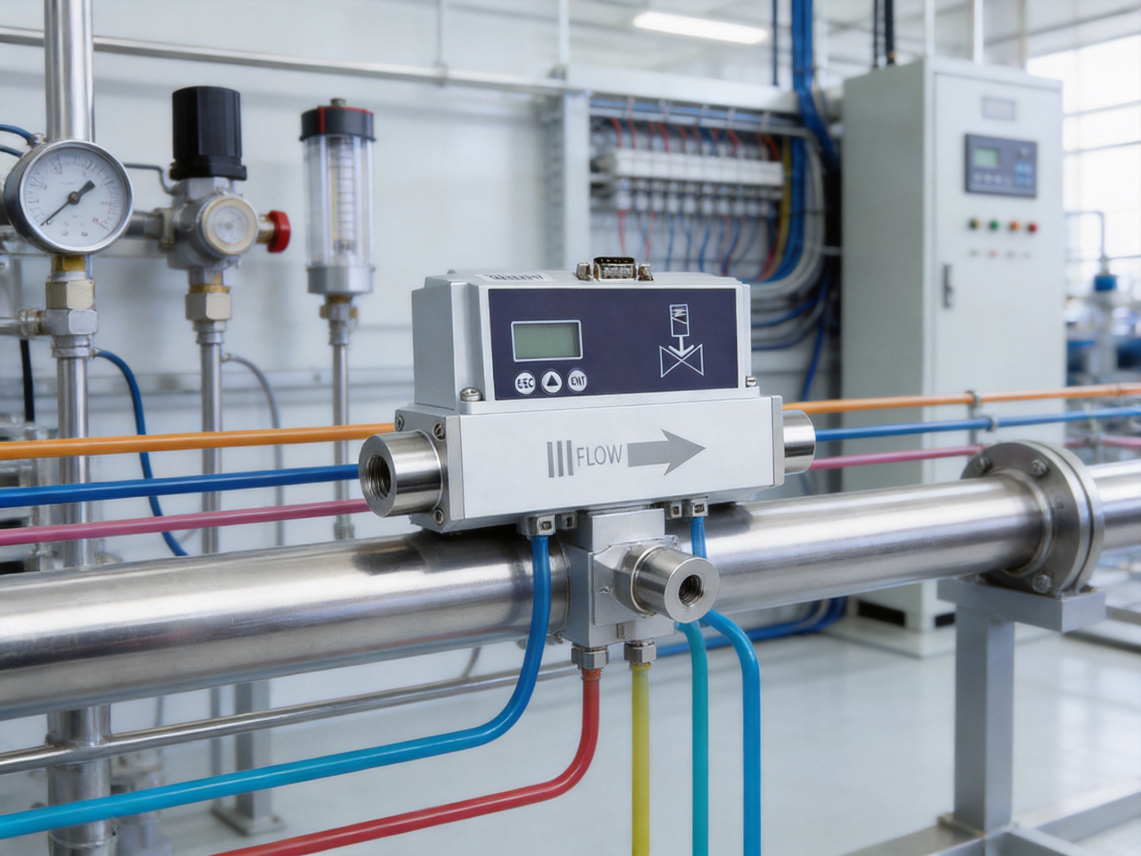
Accurate gas measurement and stable flow regulation are essential in modern industrial production. Whether a process uses air, nitrogen, oxygen, methane, argon, carbon dioxide, helium, hydrogen, or propane, the ability to measure and control gas flow directly affects product quality, operating efficiency, equipment protection, and workplace safety. For applications that require both real-time measurement and automatic flow adjustment, a thermal gas mass flow meter with an integrated proportional valve offers important advantages over a conventional flow sensor, rotameter, or separate measurement-and-control arrangement.
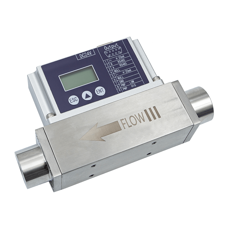
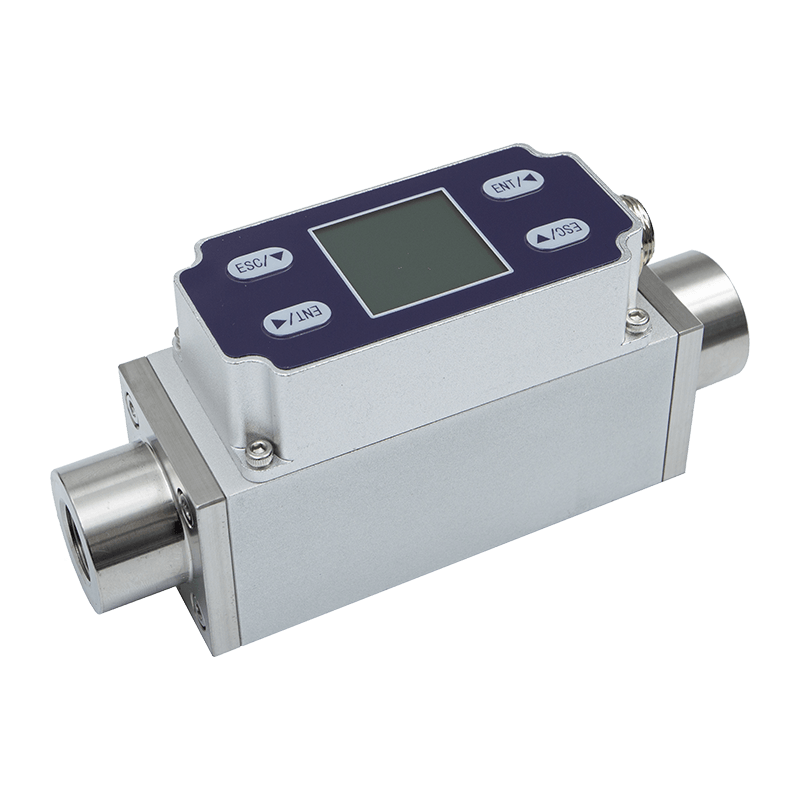
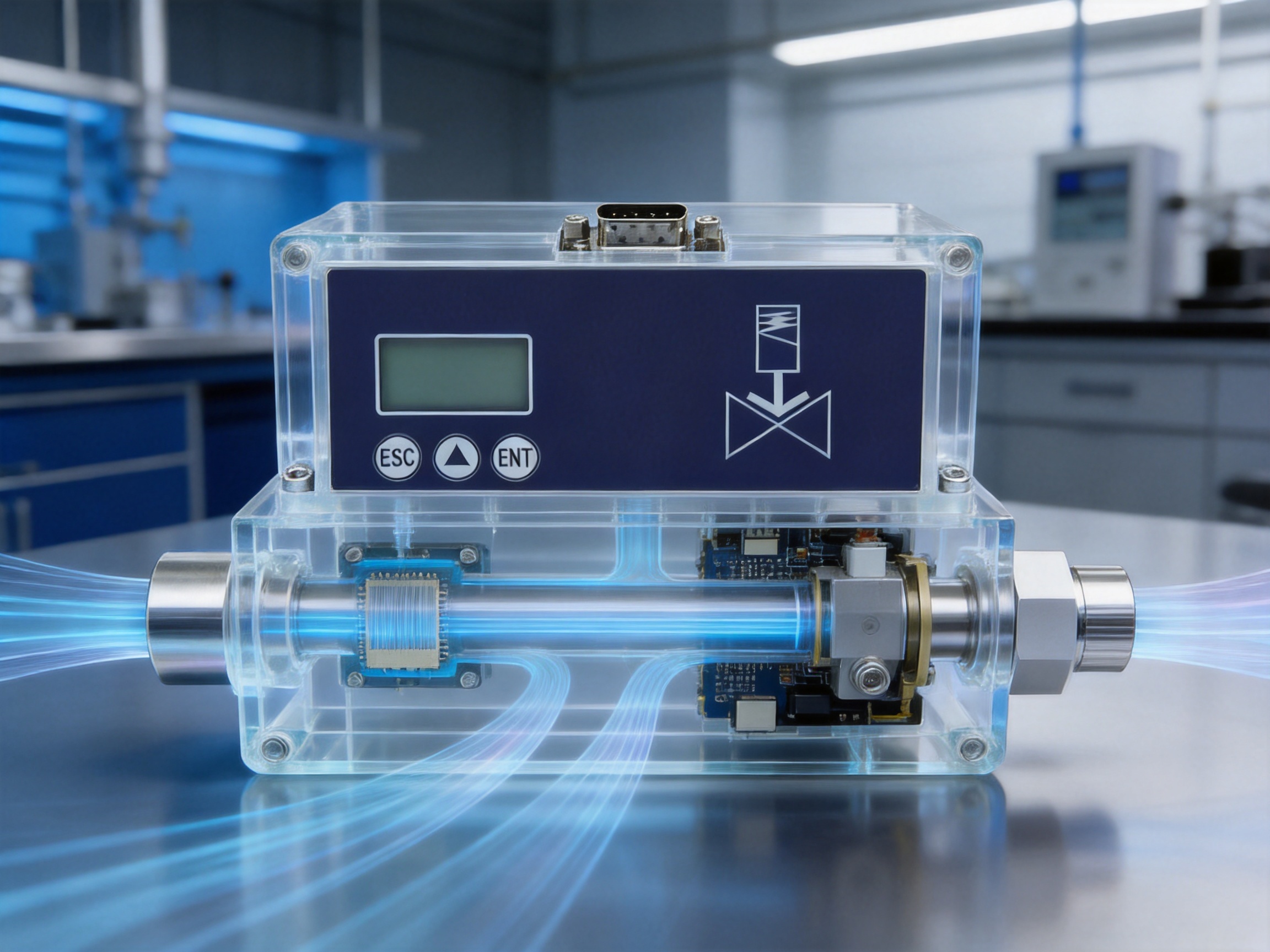
The AI-FC proportional valve control thermal gas mass flow meter is designed for precise measurement and process control of small-flow clean gases. It combines a MEMS thermal flow-sensing chip, a bypass shunt structure, digital signal processing, flow-control algorithms, and an electromagnetic proportional valve in one integrated instrument. This architecture allows the device to measure the actual gas flow and regulate the flow setpoint through the same compact system.
With a control accuracy of ±1.0% of setpoint and a measurement accuracy of 1% full scale, the instrument is suitable for applications where stable and repeatable gas delivery is more important than simple indication alone. Its 1:100 control-to-measurement range ratio, response time of less than 50 milliseconds for measurement, and typical control response time below 1.5 seconds provide a practical combination of precision, speed, and operating flexibility.
The meter is powered by DC24V and has a rated power consumption of 12W. It supports local button operation, RS485 communication using the Modbus RTU protocol, and standard 4–20mA input and output control. Depending on project requirements, 0–5V or 0–10V control interfaces can also be customized. An integrated LCD provides a direct view of instantaneous and cumulative flow, the configured flow value, and the controlled real-time flow.
Produced by ASY Electronics (JiaXing) Co., Ltd., the product reflects the company’s focus on industrial sensing, intelligent connectivity, and automation-oriented hardware. The company develops products for smart factories, equipment monitoring, energy management, and production process optimization. Its wider product portfolio includes broadband power line communication equipment, wireless temperature monitoring systems, industrial transmitters, flow meters, and automatic door controllers.
Why Integrated Gas Measurement and Control Matters
Many industrial systems require gas flow to remain within a narrow operating range. A process may depend on a stable mixture ratio, a repeatable purge volume, a consistent combustion supply, or carefully controlled gas injection. If gas flow is only measured but not automatically corrected, pressure changes, valve characteristics, temperature variation, and upstream disturbances can cause the actual flow to differ from the intended value.
A separate flow meter and manual control valve can perform these functions, but the arrangement normally requires additional piping, wiring, calibration, control logic, and installation space. The operator or host controller must also coordinate the measurement signal with the control valve. Every additional component creates another potential source of error, leakage, delay, or maintenance demand.
The AI-FC combines measurement and regulation in a single instrument. The thermal sensor detects the flow, the internal processing system compares the measured value with the target value, and the proportional valve adjusts the gas passage. This closed-loop operating concept helps the system respond to changes and maintain the desired flow more consistently than a purely manual arrangement.
The integrated structure also simplifies system design. A user can connect the instrument to a supervisory controller through RS485, use an analog signal for traditional industrial control, or set and monitor the flow through the front-panel buttons and LCD. These options make the meter adaptable to both standalone equipment and networked automation systems.
Core Measurement Technology
The instrument uses a microelectromechanical system, or MEMS, thermal flow sensor chip. MEMS technology allows the sensing element and related structures to be manufactured at a small scale with consistent geometry. A small thermal sensor can respond rapidly to the movement of gas, making it suitable for applications that require fast measurement feedback.
Thermal mass flow measurement determines flow according to the heat-transfer effect produced by moving gas. The relationship between heat input, temperature difference, and gas movement allows the sensor to respond to mass flow rather than relying only on a mechanical displacement. This is useful in industrial gas applications because mass-based measurement can provide a more meaningful process value when pressure and temperature change.
The product uses a bypass shunt structure. Instead of forcing the entire process flow directly across the sensing chip, the internal flow path distributes a controlled portion of the gas through the measurement channel. The product description specifies that the bypass fluid in the distributor remains in a laminar flow state. A stable, orderly flow profile helps improve measurement consistency and supports repeatable control performance.
The bypass approach also makes it possible to extend the instrument’s usable flow range while keeping the sensing element compact. The available specifications range from low SCCM capacities to larger SLM capacities. Configurations include 0–10, 20, 30, 50, 100, 200, 300, and 500 SCCM; 0–1, 2, 3, 5, 10, 20, and 30 SLM; 0–50 and 0–100 SLM; and 0–200 and 0–300 SLM.
Because different gases have different thermal properties, gas selection is an important part of configuration. The instrument supports selectable gas types including air, nitrogen, oxygen, methane, argon, carbon dioxide, helium, hydrogen, and propane. Users should select the correct gas type and confirm the required operating conditions during ordering and commissioning.
Integrated Electromagnetic Proportional Valve
The electromagnetic proportional valve is the central control element of the AI-FC meter. Unlike a simple on-off solenoid valve, a proportional valve can adjust its opening in response to a control signal. This allows the instrument to regulate a range of flow values rather than only switching between fully open and fully closed states.
The valve is normally closed. This configuration can provide an additional safety benefit when power is removed, because the gas path is designed to close rather than remain open. The exact safety suitability depends on the complete system design, the gas being used, and the applicable risk assessment, but the normally closed arrangement is valuable for applications where uncontrolled gas release must be minimized.
According to the supplied product information, the electromagnetic proportional valve is characterized by long service life and high sensitivity. Its integration with the sensor and control algorithm reduces the need for a separate external actuator. The result is a compact closed-loop module capable of receiving a target flow value and regulating the gas supply automatically.
The control accuracy is specified as ±1.0% SP, where SP means setpoint. This specification indicates that the controlled flow is intended to remain close to the requested value within the stated operating conditions. Measurement accuracy is listed as 1% FS, or 1% of full scale. Users should distinguish these two values when selecting a range: setpoint accuracy relates to control performance, while full-scale accuracy relates to the measurement range of the selected model.
Advantages Compared with Conventional Alternatives
One Instrument Instead of Multiple Components
A conventional installation may require a flow sensor, a separate control valve, an actuator driver, a signal converter, and a local display. The AI-FC integrates these functions into one instrument. This can reduce panel space, simplify piping, and shorten wiring routes. Fewer components can also make commissioning easier because the measurement and control functions are designed to operate together.
Closed-Loop Control Instead of Manual Adjustment
A rotameter or similar visual indicator can show an approximate flow value, but the operator must manually adjust a valve when the process changes. In contrast, the AI-FC continuously compares measured flow with the desired value and adjusts its proportional valve. This is particularly useful where pressure fluctuations or changing demand could otherwise cause the actual flow to drift.
Fast Measurement Response
The specified measurement response time is less than 50 milliseconds. Fast measurement feedback helps the control system identify changes quickly. This does not mean that every process will reach a new target in 50 milliseconds, because the typical control response time is specified separately as less than 1.5 seconds at T90. Nevertheless, the fast sensor response gives the control algorithm timely information with which to regulate the valve.
Wide Usable Range
The control and measurement range ratio is 1:100. A broad turndown capability allows one instrument to manage a wider range of process requirements without changing hardware during normal operation. This can be helpful in equipment that has low-flow standby conditions and higher-flow production stages.
Digital and Analog Integration
Some factories are built around analog control loops, while newer production lines use industrial communication networks. The AI-FC supports both approaches. Standard 4–20mA input and output are available for conventional control systems, while RS485 with Modbus RTU supports digital parameter setting, measurement reading, and integration with programmable logic controllers, industrial computers, and supervisory systems.
Direct Local Visibility
The LCD display provides a clear local indication of instantaneous and cumulative flow. Operators do not need to depend entirely on a remote control cabinet to verify operating status. Button operation also allows the flow to be controlled locally when appropriate. This combination supports maintenance, commissioning, troubleshooting, and standalone operation.
Stable Measurement Through a Bypass Flow Path
The specified laminar bypass flow structure contributes to stable measurement and control. A controlled internal distribution path helps the thermal sensing element operate under consistent flow conditions. This is an important distinction from simple mechanical indicators whose readings can be more sensitive to installation position, visual interpretation, or moving mechanical parts.
Technical Specifications
Parameter | Specification |
Product type | Proportional valve control thermal gas mass flow meter |
Model description | AI-FC |
Power supply | DC24V |
Power consumption | 12W |
Control accuracy | ±1.0% SP |
Measurement accuracy | 1% FS |
Control-to-measurement range ratio | 1:100 |
Valve type | Normally closed electromagnetic proportional valve |
Operating temperature | -10°C to 55°C |
Humidity | Below 95% RH, without frost, ice, or condensation |
Measurement response time | Less than 50 ms |
Typical control response time | Less than 1.5 seconds at T90 |
Standard output | 4–20mA, equivalent 1–5V |
Optional or customized output | 0–5V and 0–10V |
Communication | RS485 using Modbus RTU |
Mechanical connections | G1/4 and PT1/2 internal threads; other threads available by customization |
Protection level | IP40 |
The listed technical values should be considered together with the selected flow range, gas type, pressure, temperature, installation conditions, and calibration requirements. The product data states that measurements were made at 25°C, 101.32kPa, and in dry air. Actual results may vary when the instrument is used under different conditions or with a gas that has different physical properties.
Flow Range and Pressure Selection
Correct range selection is one of the most important steps in applying any mass flow meter. The instrument is available in multiple ranges, beginning with low SCCM capacities and extending to hundreds of SLM. A model should be selected so that the normal operating point is comfortably within the usable range rather than permanently near the minimum or maximum limit.
The stated measurement pressure range is 0–1.5MPa. Control pressure conditions depend on the selected flow specification. For configurations from 10 SCCM to 30 SLM, the listed control pressure range is 0.1–1.0MPa. For the 100 SLM version, the listed pressure range is 0.1–0.65MPa. For the 300 SLM version, the listed pressure range is 0.1–0.5MPa.
The normal operating pressure difference is also related to flow. For flow rates up to and including 30 SLM, the listed pressure difference is 0.1–0.8MPa. For flow rates above 30 SLM and up to 100 SLM, the listed range is 0.1–0.6MPa. For flow specifications above 100 SLM and below 300 SLM, the listed range is 0.1–0.4MPa.
These pressure requirements should be reviewed before installation. The upstream supply must provide sufficient pressure for the intended flow, while the downstream process must remain within the allowable pressure conditions. Pressure regulators, filters, shutoff valves, and relief devices may be needed as part of the complete gas delivery system.
Gas Compatibility and Reference Conditions
The AI-FC supports several commonly used industrial gases. Available selections include air, nitrogen, oxygen, methane, argon, carbon dioxide, helium, hydrogen, and propane. Each gas has different density, thermal conductivity, heat capacity, and safety characteristics. Selecting the correct gas setting is necessary for accurate thermal mass measurement.
The instrument provides selectable standard temperature conditions of 0°C, 20°C, and 25°C. The standard condition can be adjusted by the user, with 25°C listed as the default. This feature is important because standard volumetric flow values depend on the reference temperature and pressure used for conversion.
Users should define whether the process specification is expressed in SCCM, SLM, or another unit and should confirm the reference conditions associated with that unit. A mismatch between the flow unit used by the process and the standard condition configured in the meter can create an apparent discrepancy even when the sensor is operating normally.
For oxygen, hydrogen, methane, propane, and other gases with special flammability or oxidation risks, the complete installation must follow appropriate safety procedures. Materials, seals, cleaning, ventilation, electrical classification, and leak testing should be evaluated by qualified personnel. The IP40 protection rating is intended for suitable indoor or protected industrial environments and should not be interpreted as a hazardous-area certification.
Communication and Control Options
Local Button Operation
The front-panel button interface allows users to set and control flow without necessarily connecting a separate host controller. This is useful during installation, calibration checks, laboratory operation, machine commissioning, and maintenance. The LCD provides immediate visual feedback of the operating state and flow value.
4–20mA Analog Control
4–20mA is widely used in industrial automation because it is relatively resistant to voltage drop and electrical interference over long cable runs. The AI-FC supports standard 4–20mA input and output control, with the output also represented as 1–5V in the supplied specifications. This allows the instrument to connect with PLC analog modules, distributed control systems, process controllers, and other industrial equipment.
RS485 and Modbus RTU
RS485 communication enables multiple devices and longer industrial communication links to be arranged using a robust differential signaling method. The AI-FC uses the Modbus RTU protocol, which is widely supported by PLCs, human-machine interfaces, industrial computers, and data acquisition systems. Digital communication can provide access to flow values, cumulative flow, configuration data, status information, and control commands according to the implemented register map.
Customized Voltage Interfaces
Some equipment platforms use voltage-based control rather than current loops. For these systems, 0–5V or 0–10V input and output control can be customized. This flexibility reduces the need for external signal converters and helps the meter match the electrical architecture of existing equipment.
Manufacturing and Engineering Strengths
The performance of a thermal mass flow meter depends not only on the sensor chip but also on the quality of mechanical design, flow-channel manufacturing, electronics assembly, calibration, software, and final inspection. ASY Electronics positions its products around data sensing and intelligent connectivity, providing a foundation for integrating the AI-FC into broader industrial automation systems.
The use of a MEMS sensor chip requires controlled manufacturing and careful electronic integration. Small changes in sensing geometry, thermal characteristics, soldering quality, signal conditioning, and protective assembly can influence measurement performance. A product-oriented manufacturing process must therefore manage both precision electronics and gas-path mechanics.
The bypass shunt and internal flow path also require attention to dimensional consistency. The distributor must divide gas flow predictably and maintain suitable flow behavior across the measurement range. Stable internal geometry contributes to repeatability from unit to unit and supports reliable calibration.
The integrated proportional valve introduces another engineering discipline. The valve must respond sensitively to the control signal while maintaining stable operation over repeated cycles. The normally closed construction, valve driver, control algorithm, and mechanical sealing system must work together. This integration is more demanding than simply installing a separate manual valve beside a sensor.
Digital signal processing and flow-control algorithms are additional strengths of the product design. The system does not merely produce a raw sensor output; it interprets the sensing signal, applies configured gas and reference conditions, compares actual flow with the target value, and generates an appropriate valve-control response. This combination of hardware and software is central to achieving fast response and stable regulation.
ASY Electronics’ broader focus on industrial data integration supports the development of products intended for connected factories. The flow meter can be used as an individual instrument, but it can also become a data source within a larger system that monitors equipment condition, energy use, gas consumption, and production performance.
The company’s wider product range in power line communication, wireless temperature monitoring, industrial transmitters, and automatic door controllers indicates experience across sensing, communication, and industrial control. This cross-domain capability can be useful for customers seeking a coordinated supplier rather than isolated devices from multiple vendors.
Installation Considerations
The AI-FC is supplied with standard mechanical interfaces including G1/4 and PT1/2 internal threads. Other thread types can be customized. Before installation, users should confirm thread standards, sealing methods, pipe size, flow direction, pressure rating, and the compatibility of all wetted materials with the selected gas.
Gas piping should be clean and free of particles, oil, moisture, and construction debris. Contamination may affect the sensor, valve, or internal flow distributor. A suitable upstream filter may be required, especially in systems where compressors, regulators, or flexible hoses can introduce particles or oil aerosols.
The meter should be installed in a location where the ambient temperature remains within -10°C to 55°C and where condensation, frost, and ice are avoided. The specified humidity limit is below 95% RH without frost, ice, or condensation. Although the instrument has an IP40 enclosure rating, it should be protected from direct water spray, heavy dust, corrosive atmospheres, and outdoor weather unless an appropriate enclosure is provided.
Pipe routing should avoid sudden disturbances close to the meter where possible. Elbows, tees, partially closed valves, regulators, and reducers can create turbulence or pressure instability. A well-designed installation provides stable upstream and downstream conditions and follows the equipment supplier’s recommendations for straight pipe sections and flow direction.
Electrical wiring should use the correct DC24V supply and suitable grounding practices. Analog signal cables should be routed away from high-power switching lines where possible. For RS485 communication, correct polarity, cable termination, network addressing, and shield practices should be observed. The electrical installation should be completed by qualified personnel in accordance with local standards.
Application Areas
Gas Mixing and Blending
Gas mixing systems often require multiple flow channels to deliver repeatable proportions. The AI-FC can regulate an individual gas stream while reporting real-time and cumulative flow to the control system. Its selectable gas configurations and broad range of available capacities make it suitable for laboratory-scale and industrial process equipment, subject to pressure and compatibility verification.
Analytical and Laboratory Equipment
Analytical instruments frequently need a stable carrier, purge, or calibration gas. Compact dimensions, fast measurement feedback, local display, and digital communication can simplify integration into analyzers and test equipment. The normally closed valve can also help prevent unwanted gas flow when the instrument is powered down, subject to the requirements of the complete apparatus.
Fuel and Combustion Systems
Air and fuel gas flow must be controlled carefully in combustion processes. The AI-FC may be considered for suitable clean-gas applications where its pressure, temperature, flow, and safety specifications are met. Combustion applications require additional safeguards, including flame detection, shutoff systems, ventilation, pressure protection, and compliance with applicable regulations.
Semiconductor and Electronics Manufacturing
Electronics production can require controlled gas delivery for equipment purging, process protection, coating, drying, or specialized manufacturing steps. Cleanliness, gas compatibility, pressure stability, and material suitability must be evaluated for each process. The fast sensor response and digital connectivity are beneficial where flow data must be incorporated into equipment monitoring or recipe control.
Energy and Process Monitoring
Flow meters can support energy management by recording gas consumption and identifying abnormal usage. The cumulative flow display provides local consumption information, while RS485 communication can transfer operating data to a supervisory platform. When combined with temperature sensors, transmitters, and communication devices, gas flow information can contribute to a more complete industrial energy profile.
Equipment Condition and Production Monitoring
A changing gas-flow pattern may indicate a clogged filter, pressure problem, valve fault, leakage, or process interruption. By collecting instantaneous and cumulative flow data, an industrial monitoring system can establish normal operating patterns and generate alerts when values move outside expected limits. This supports preventive maintenance and helps reduce unplanned downtime.
Commissioning and Operating Recommendations
Before commissioning, verify the selected gas type, standard temperature, flow range, pressure conditions, mechanical connections, and signal configuration. Confirm that the upstream gas supply is clean and that all connections have been leak-tested. If the application uses a hazardous, flammable, oxidizing, or toxic gas, complete the required risk assessment and safety review before introducing gas.
Apply DC24V power within the specified requirements and allow the instrument to stabilize according to the project commissioning procedure. Confirm that the display operates normally and that the selected flow unit and gas type are correct. If the device is connected through RS485, verify communication parameters, device address, register settings, and data scaling.
Introduce gas gradually and confirm that the measured value responds in the expected direction. Set a low initial flow value and compare the local display with the host controller. Then test several operating points across the normal process range. This helps confirm that the instrument, piping, analog signal, and communication system are working together correctly.
Do not exceed the specified pressure or flow range. A flow meter should not be used as a substitute for an independent pressure-relief system or emergency shutoff system. Where the process requires a specific safety function, that function should be implemented using appropriately rated equipment and a validated control architecture.
Maintenance and Long-Term Reliability
The AI-FC is designed with a MEMS sensor and an electromagnetic proportional valve, avoiding the mechanical float arrangement found in many basic flow indicators. This can reduce dependence on moving visual components, but all gas instruments still require suitable maintenance.
Maintenance intervals depend on gas cleanliness, operating pressure, duty cycle, humidity, and process contamination. Users should inspect filters, tubing, seals, electrical connections, communication status, and displayed flow values at intervals appropriate for the application. Any abnormal noise, unstable flow, unexpected zero drift, slow response, or inability to reach the setpoint should be investigated.
Where the gas contains particles, oil, condensable vapor, or corrosive components, upstream treatment may be necessary. If the process is interrupted for an extended period, the meter should be isolated according to the site procedure. Do not disassemble the gas path or attempt internal repairs without authorization from qualified technical personnel.
Calibration verification can be performed using a suitable reference device or approved test procedure. Because the stated accuracy is based on specified reference conditions, the verification method should account for gas type, temperature, pressure, and standard flow definitions. A documented calibration program can help maintain process confidence and support quality-system requirements.
How the Product Supports Smart Factory Development
Smart manufacturing depends on reliable data from the equipment layer. A gas flow meter that can measure, control, display, and communicate provides more than a local process indication. It becomes an intelligent field device capable of contributing to production data, energy analysis, alarm management, and equipment diagnostics.
The AI-FC can provide instantaneous flow information for real-time control and cumulative flow information for usage analysis. Modbus communication allows these values to be collected by a central system. When connected with other industrial transmitters and sensor networks, the data can be correlated with temperature, pressure, machine status, production output, and energy consumption.
This type of integration supports refined energy management. A factory can compare gas consumption among machines, identify off-shift consumption, calculate usage per production unit, and investigate deviations from normal behavior. Better visibility can help reduce waste and improve maintenance planning.
ASY Electronics’ company mission centers on efficient, reliable, and green smart factories. Its products are designed around data sensing and intelligent connectivity, matching the direction of industrial digitalization. The AI-FC therefore fits into a wider product strategy rather than functioning only as an isolated measurement instrument.
Selection Checklist for Buyers
Before ordering, define the gas type and confirm whether it is included in the supported gas list. Specify the minimum, normal, and maximum required flow. Select a model whose range covers the process without operating continuously at an unsuitable limit.
Confirm upstream and downstream pressure, required pressure drop, ambient temperature, humidity, and the applicable standard reference temperature. Identify the desired mechanical thread, flow direction, installation orientation, and any required customized connections.
Choose the control method: local buttons, Modbus RTU, 4–20mA, or a customized 0–5V or 0–10V interface. Confirm whether analog input and output scaling match the host system. For RS485 installations, request the communication register map and verify the required baud rate, parity, address, and wiring arrangement.
Review whether the IP40 protection level is suitable for the installation environment. If the instrument will be used outdoors, in a washdown area, or in a classified hazardous location, discuss the need for an additional enclosure or a different certified product with the supplier.
Frequently Asked Questions
What does the AI-FC measure?
The AI-FC measures and controls the mass flow of selected clean gases. Supported gas selections include air, nitrogen, oxygen, methane, argon, carbon dioxide, helium, hydrogen, and propane.
What is the control accuracy?
The specified control accuracy is ±1.0% of setpoint. Measurement accuracy is specified as 1% of full scale. These values describe different performance aspects and should be evaluated according to the selected flow range and application conditions.
What is the response time?
The measurement response time is less than 50 milliseconds. The typical control response time is less than 1.5 seconds at T90. Actual process response depends on gas pressure, pipe volume, valve conditions, target flow, and system configuration.
Is the valve normally open or normally closed?
The valve is normally closed. It is designed to close the gas path when the valve is not energized, subject to the complete equipment design and the applicable operating conditions.
Can the flow meter communicate with a PLC?
Yes. The product supports RS485 communication using the Modbus RTU protocol. It also supports standard 4–20mA input and output control. Voltage interfaces of 0–5V or 0–10V can be customized.
Can the flow be adjusted locally?
Yes. The product includes button operation and an LCD display. Users can set and monitor flow locally, while the display provides instantaneous and cumulative flow information.
What power supply is required?
The specified working power supply is DC24V, with a rated power consumption of 12W.
What flow ranges are available?
Available configurations extend from low-flow ranges such as 0–10 SCCM to larger ranges including 0–300 SLM. Specific listed options include several SCCM, SLM, and higher-capacity ranges. The correct model should be selected according to the required gas, pressure, and normal operating flow.
What mechanical connections are standard?
Standard mechanical connections include G1/4 and PT1/2 internal threads. Other thread types may be available through customization.
What are the reference measurement conditions?
The supplied specifications state that measurements were made at 25°C, 101.32kPa, and in dry air. The instrument also provides selectable standard temperature conditions of 0°C, 20°C, and 25°C, with 25°C as the default.
Is the meter suitable for every gas installation?
No. Suitability depends on gas compatibility, cleanliness, pressure, temperature, flow range, safety requirements, and local regulations. Flammable, oxidizing, toxic, or high-risk gases require a complete engineering and safety assessment.
How does this product compare with a rotameter?
A rotameter generally provides local visual indication and usually requires manual adjustment. The AI-FC combines electronic measurement, automatic proportional-valve control, a local LCD, analog interfaces, and Modbus communication. This makes it more suitable for automated and data-connected processes.
How does it compare with a separate flow meter and control valve?
The integrated design reduces the number of separate components and coordinates measurement with control in one device. It can simplify installation and control architecture, although the final choice should consider the required flow range, certification, redundancy, and process safety requirements.
Conclusion
The AI-FC proportional valve control thermal gas mass flow meter is designed for industrial applications that require accurate measurement, automatic regulation, local visibility, and digital connectivity. Its MEMS thermal sensor, laminar bypass shunt, electromagnetic proportional valve, digital processing, and control algorithms create an integrated solution for small-flow clean-gas management.
With ±1.0% SP control accuracy, 1% FS measurement accuracy, a 1:100 control-to-measurement range ratio, less than 50ms measurement response, and typical control response below 1.5 seconds, the meter offers a balanced performance profile for automated equipment. Its selectable gas types, multiple flow ranges, standard 4–20mA interfaces, RS485 Modbus RTU communication, customizable voltage signals, and LCD display provide flexibility for both standalone and networked installations.
Compared with manual indicators or separate measurement-and-control assemblies, the integrated design can reduce system complexity while improving feedback and operating visibility. The product also aligns with the requirements of smart factories by providing real-time and cumulative flow data for production control, energy management, maintenance, and process optimization.
Supported by ASY Electronics’ capabilities in industrial sensing, intelligent connectivity, and data integration, the AI-FC is positioned as a practical field device for modern gas-management systems. Proper range selection, installation, gas compatibility review, and safety engineering remain essential, but when applied within its specified conditions, the meter can provide a reliable foundation for precise and connected industrial flow control.
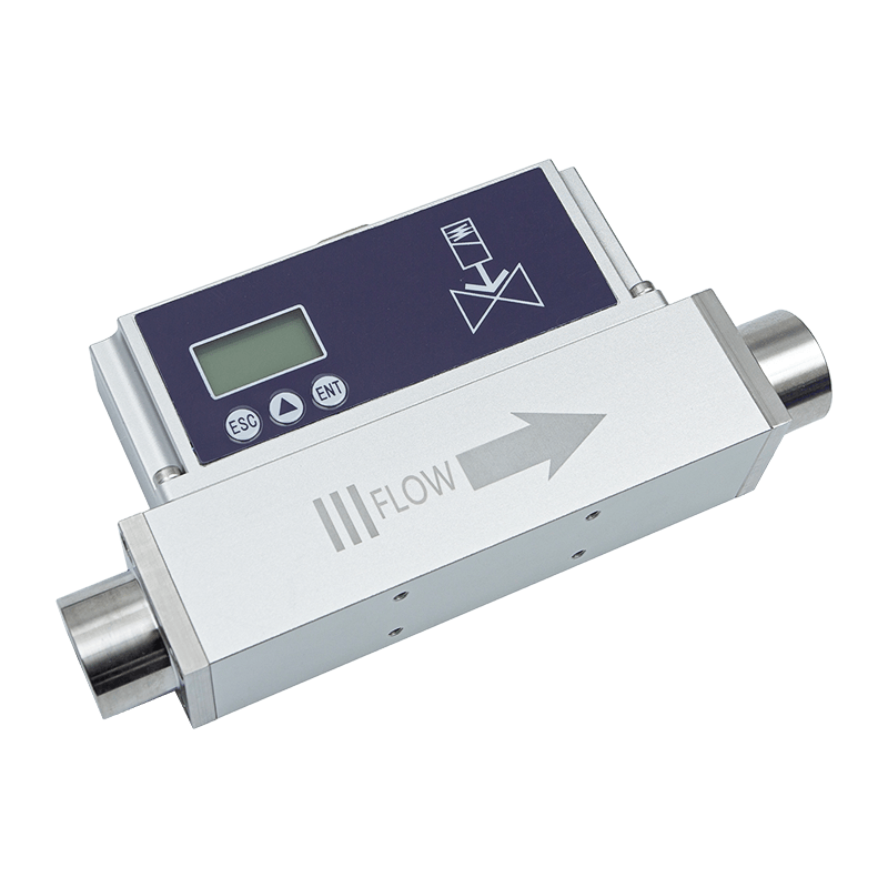
Proportional Valve Control Type Thermal Gas Mass Flowmete
References
1. Product technical information for the AI-FC proportional valve control thermal gas mass flow meter.
2. Product specifications covering MEMS thermal sensing, bypass shunt flow measurement, proportional valve control, communication interfaces, and available flow ranges.
3. Industrial instrumentation principles for thermal mass flow measurement and closed-loop gas-flow control.
4. General engineering practices for RS485 and Modbus RTU industrial communication.
5. General guidelines for industrial gas piping, pressure management, leak testing, and equipment commissioning.
6. General principles of smart factory sensing, industrial data integration, and energy-management monitoring.
7. ASY Electronics company information concerning industrial sensing, intelligent connectivity, power line communication, wireless temperature monitoring, transmitters, flow meters, and automatic door controllers.