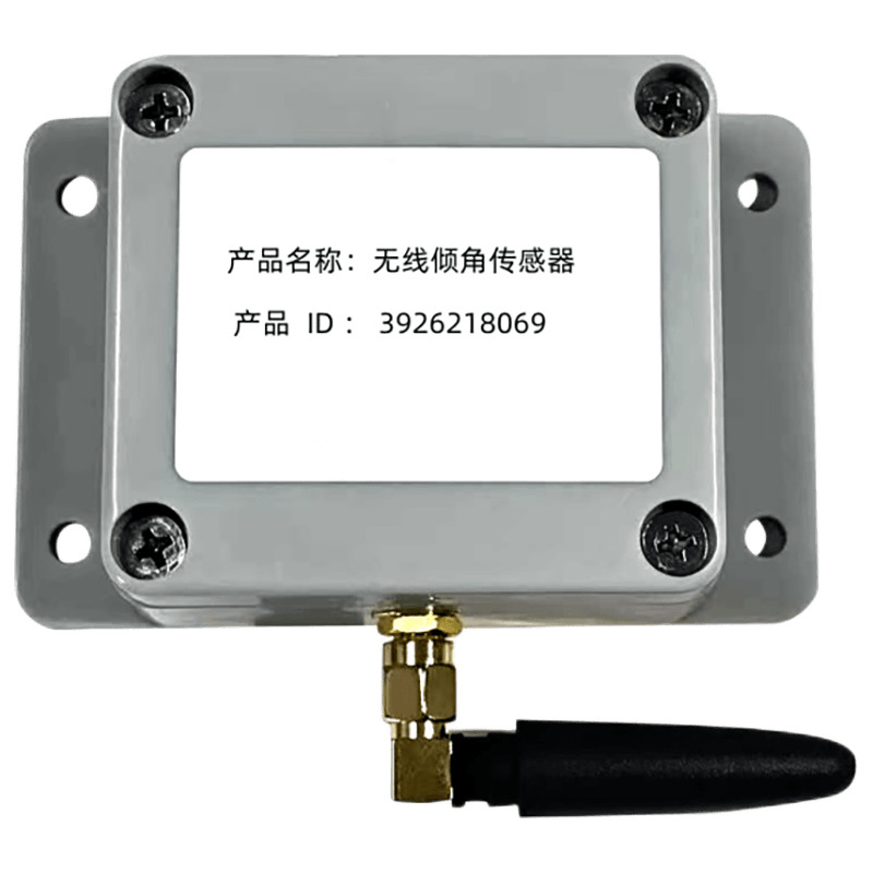


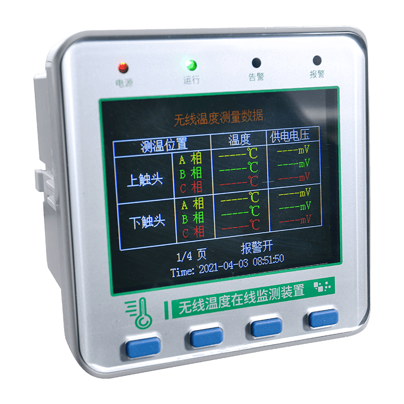

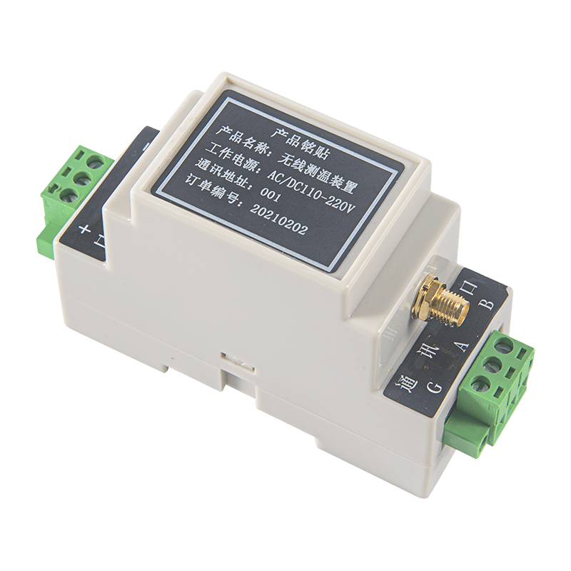

Industrial facilities increasingly depend on continuous temperature information to protect electrical equipment, rotating machinery, process systems, storage areas, and critical production assets. Conventional inspection methods, including manual thermometer readings and periodic infrared checks, can identify only temporary conditions. They may also miss rapid temperature increases, intermittent overheating, or abnormal conditions that develop between inspection rounds. A wireless temperature monitoring host provides a practical way to collect sensor data continuously and make that information available to supervisory systems.
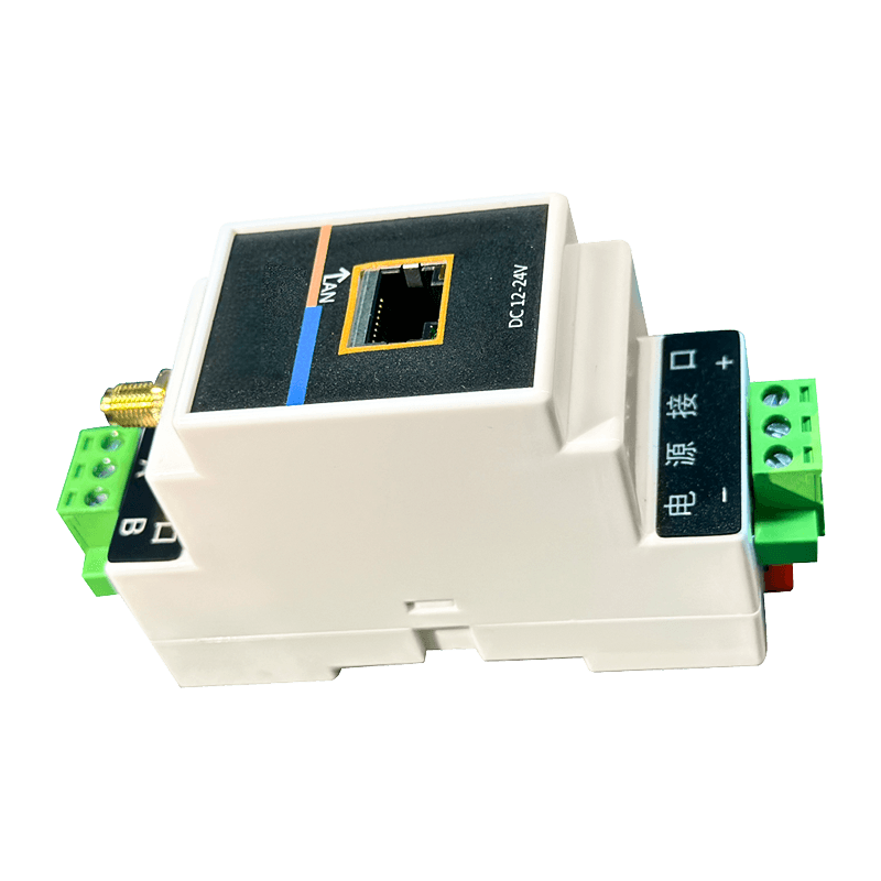
The KS30M-LORA is a DIN rail-mounted wireless temperature measurement host designed for industrial temperature monitoring applications. It receives temperature and voltage data from wireless sensors and makes the information available through RS485 communication. With support for standard MODBUS RTU communication, two-channel RS485 communication output, relay dry contacts, and a capacity of up to 240 sensors, the unit can serve as the central receiving device in a scalable monitoring network.
Its metal enclosure, wide AC/DC power input, industrial environmental range, Sub-GHz wireless communication, and flexible installation methods make it suitable for power distribution systems, petroleum facilities, chemical plants, railways, mines, metallurgy operations, cement production, and other industrial environments. More than a simple receiver, it is an interface between field temperature sensors, control equipment, industrial networks, and plant-level data systems.
Why Wireless Temperature Monitoring Matters in Industry
Temperature is one of the most useful indicators of equipment condition. An abnormal rise may signal excessive electrical resistance, loose connections, overloaded conductors, bearing wear, insufficient lubrication, blocked ventilation, process instability, or deterioration of insulation. When temperature information is collected continuously, maintenance teams can respond before a localized fault develops into an outage, fire, production interruption, or major equipment failure.
Traditional wired measurement systems can provide reliable data, but installing wires on high-voltage conductors, moving mechanisms, enclosed busbars, rotating equipment, or widely distributed assets can be difficult. Cabling may require shutdowns, additional conduits, insulation measures, and extensive labor. In some applications, the physical installation of a cable is more complicated than the temperature measurement itself.
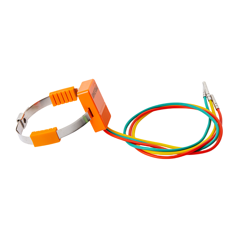
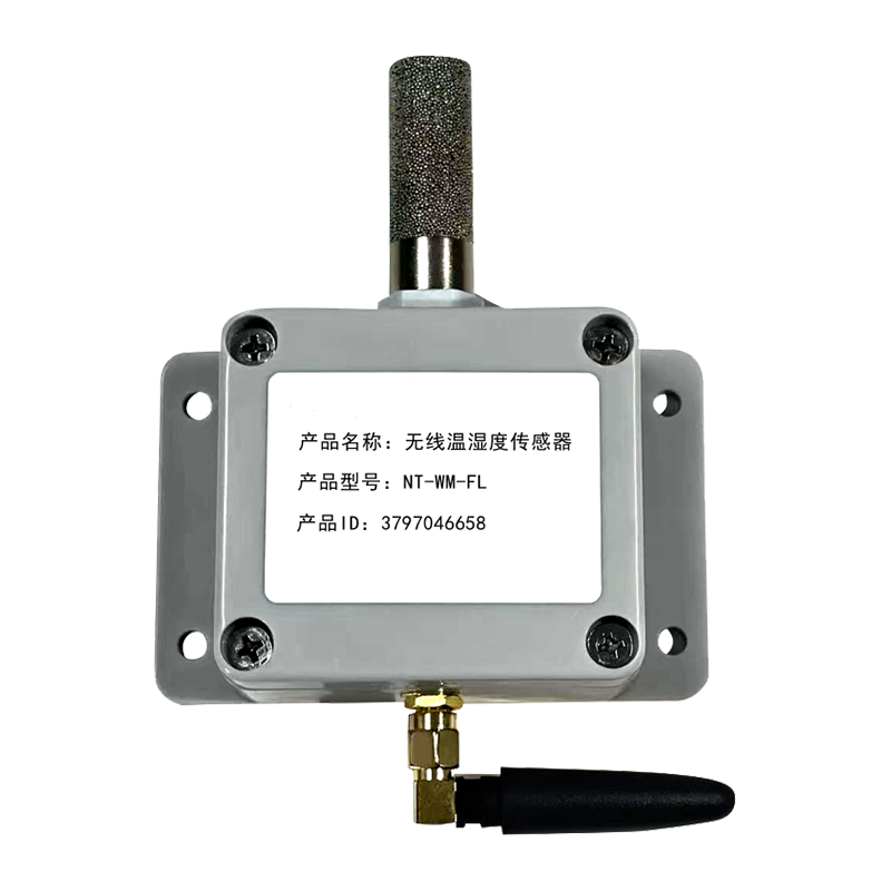
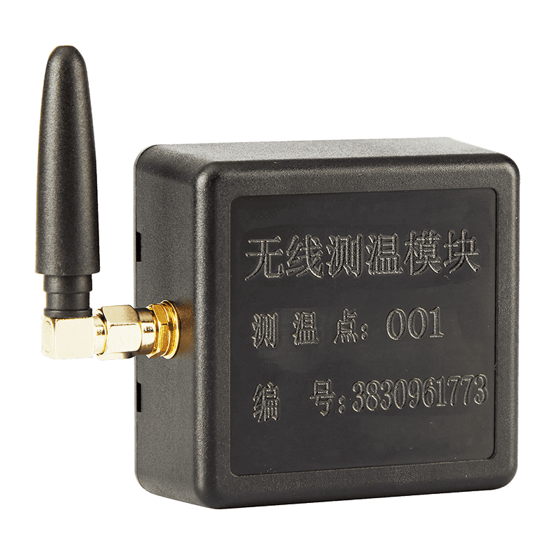
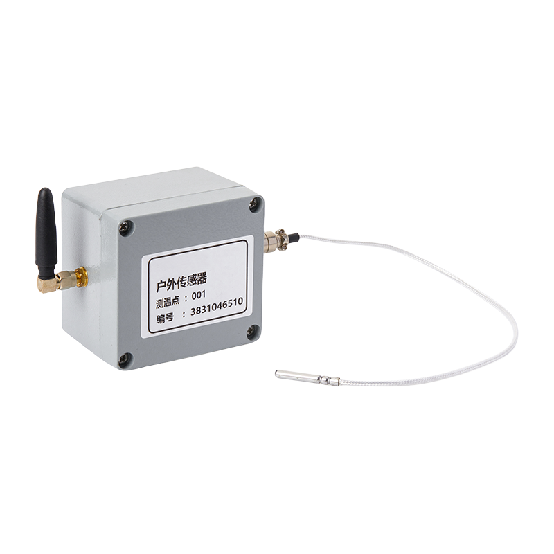
A wireless architecture reduces the amount of field wiring required. Wireless sensors can be placed directly on or near the equipment being monitored, while the receiving host is installed in a suitable control cabinet or electrical enclosure. The host collects the sensor information and transfers it to a PLC, building management system, energy management platform, SCADA system, or industrial computer.
The wireless approach also supports phased deployment. A facility can begin with a small number of sensors on its most important assets and expand the system as monitoring requirements grow. The KS30M-LORA can receive data from up to 240 sensors, allowing one host to support a relatively large monitoring zone when radio planning and installation conditions are appropriate.
Product Overview
The KS30M-LORA is an industrial-grade wireless temperature measurement host with a metal enclosure designed for guide rail installation. It receives radio signals from compatible wireless temperature sensors and processes the incoming measurement information for industrial communication.
The host is intended to be positioned between wireless field sensors and upper-level monitoring or control equipment. Sensors acquire temperature and voltage-related information at the measurement point. The host receives those transmissions, identifies the relevant sensor, and exposes the collected data through RS485 communication using a standard MODBUS RTU protocol.
This architecture separates the sensing function from the data integration function. Sensors can be placed where measurement is required, while the host can be mounted in a control cabinet, distribution panel, or automation enclosure. The arrangement helps reduce field wiring and provides a structured method for connecting multiple temperature points to an existing industrial network.
The unit supports a Sub-GHz wireless frequency band, with 433 MHz specified as the default frequency. Sub-GHz communication is widely used in industrial wireless applications because it can provide useful propagation characteristics in facilities containing equipment, cabinets, walls, metal structures, and other obstacles. Actual range and communication quality depend on the installation environment, antenna position, interference conditions, enclosure design, and local radio requirements.
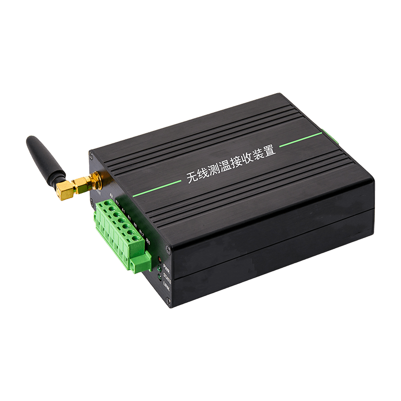
Metal Enclosure Version Guide Rail Temperature Measurement Unit
Core Technical Specifications
| Item | Specification |
| Product model | KS30M-LORA |
| Product type | Wireless temperature monitoring host |
| Enclosure | Metal enclosure |
| Installation | Guide rail installation and screw installation |
| Operating ambient temperature | -25°C to +70°C |
| Ambient humidity | Up to 95% |
| Atmospheric pressure | 80 to 110 kPa |
| Altitude | Up to 2,500 meters |
| Working power supply | AC/DC 100–240 V |
| Maximum number of sensors | 240 |
| Wireless frequency band | Sub-GHz, 433 MHz default |
| Communication interface | RS485 |
| Communication output | Two-channel RS485 communication output |
| Relay output | AC 220 V/5 A, one set of passive normally open and normally closed contacts |
| Default baud rate | 9,600 bps |
| Data format | 8 data bits, 1 stop bit |
| Verification | None by default |
| Protocol | Standard MODBUS RTU |
Metal Enclosure and DIN Rail Installation
The metal enclosure is an important part of the host’s industrial design. Compared with a lightweight general-purpose plastic receiver, a metal housing can provide a more robust mechanical structure for installation in control cabinets and equipment panels. It is suitable for environments where the product may be exposed to vibration, routine maintenance activity, cable movement, and contact with other industrial devices.
A metal enclosure also supports a professional control-panel layout. Industrial automation cabinets often contain circuit breakers, terminal blocks, power supplies, PLCs, communication gateways, and signal conditioners. A host that can be installed on a DIN rail can be positioned alongside these components without requiring a special mounting plate or custom bracket.
The KS30M-LORA supports guide rail installation and screw installation. DIN rail mounting enables fast positioning and convenient removal during service. Screw installation provides an alternative when the host must be fixed directly to a panel or another mounting surface. This flexibility is useful for original equipment manufacturers, system integrators, and maintenance teams working with different cabinet layouts.
Installation planning should include sufficient clearance for wiring, access to communication terminals, power isolation, antenna placement, and future service. The host should be installed in a location that is protected from direct water exposure, excessive condensation, corrosive chemicals, and temperatures outside the stated operating range. The metal housing is a strength, but it does not eliminate the need for appropriate cabinet design and environmental protection.
Wide Power Input for Industrial Applications
The host accepts an AC/DC 100–240 V power supply. A wide input range simplifies system design because it can accommodate common industrial and commercial power arrangements. It also reduces the need for a dedicated voltage conversion stage when the receiving host is installed in a control cabinet that already provides a suitable supply.
Power design remains important in any wireless monitoring installation. The host should be connected through suitable protection and isolation equipment, and the installer should verify that the supply wiring complies with local electrical requirements. Grounding, overcurrent protection, cabinet ventilation, and separation between power and signal wiring should be considered during installation.
For facilities with several monitoring zones, the broad input range can assist standardization. The same host model may be used in different control cabinets without redesigning the power section for every site. Standardization can reduce engineering effort, simplify spare-parts planning, and make training easier for technical staff.
Capacity for Up to 240 Wireless Sensors
One of the product’s most significant advantages is its stated ability to receive data from up to 240 sensors. This capacity allows a single host to collect information from many measurement points, reducing the number of receiving devices required in a monitoring project.
In a power distribution application, sensors may be assigned to busbar joints, cable connections, switchgear compartments, transformer connections, and other high-risk locations. In a motor or process application, sensors may be assigned to bearings, housings, electrical terminals, pipelines, valves, and local control points. The exact arrangement depends on the sensor type, application requirements, wireless plan, and equipment configuration.
A high sensor capacity can provide several practical benefits. It can reduce cabinet space, decrease the number of communication nodes connected to the supervisory system, and simplify the logical structure of the monitoring network. It also creates room for future expansion. A project may begin with the most critical assets and add sensors later without immediately replacing the receiving architecture.
Large sensor networks require disciplined identification and commissioning. Each sensor should have a unique ID, a documented physical location, a clear asset name, and an association with the relevant MODBUS data point. Good documentation is essential when hundreds of values are displayed on a monitoring platform. The host’s ID register function supports the setting of sensor IDs, helping integrators organize the sensor network.
Wireless Parameters and Sensor Matching
The wireless parameters define the relationship between the receiving host and the temperature sensors. Matching parameters must be configured correctly so that the host can recognize and process transmissions from the intended sensors. This is especially important when multiple wireless monitoring systems operate in the same facility or when several receiving hosts are installed within radio range of one another.
Commissioning should include a sensor inventory, wireless parameter verification, ID assignment, signal checking, and functional testing. The installer should confirm that each physical sensor appears under the correct logical address and that the displayed temperature corresponds to the correct equipment.
Wireless communication provides installation flexibility, but it should not be treated as a substitute for engineering. Metal cabinets, reinforced concrete, large transformers, enclosed switchgear, and dense industrial structures can influence radio propagation. The receiving host and sensor positions should therefore be evaluated at the actual site. Where necessary, the installation plan should be tested under normal operating conditions rather than relying only on open-space assumptions.
The default Sub-GHz frequency band and 433 MHz configuration offer a foundation for deployment, while the final radio configuration should comply with the requirements applicable to the installation location. System designers should also consider neighboring radio systems, antenna orientation, cabinet placement, and the potential effects of future equipment changes.
Temperature Data Accuracy and Format
The temperature parameter is defined as 16-bit data with the most significant digit first. The measurement resolution is 0.1°C, and the stated error is ±1°C. The data arrangement is suitable for structured industrial communication because a fixed register format makes it easier for PLCs, industrial computers, and monitoring platforms to interpret the received values.
A resolution of 0.1°C allows the monitoring system to display gradual changes rather than only whole-degree values. This can be useful when trending equipment behavior, comparing phases, identifying thermal imbalance, or establishing warning thresholds. The stated measurement error should be considered when setting alarm limits and evaluating the application’s risk tolerance.
Temperature values should be interpreted together with equipment design, operating load, ambient conditions, and historical trends. A single reading may not indicate a fault by itself. A gradual increase, a persistent difference between similar components, or a sudden departure from the established operating pattern can be more meaningful than an isolated value.
System integrators should verify the exact register interpretation during commissioning, including byte order, scaling, sensor address, and any model-specific data mapping. Proper register documentation helps prevent common integration errors such as reversing high and low bytes, displaying tenths of a degree as whole degrees, or assigning the wrong sensor to a monitored asset.
Voltage Parameter Monitoring
In addition to temperature, the system provides a voltage parameter in a 16-bit format with the most significant bit first. The meaning of this value depends on the sensor type. For an active sensor, the voltage value represents battery voltage. For a passive sensor, it represents the voltage after power has been rectified and regulated.
Voltage information adds an important maintenance dimension to temperature monitoring. If an active sensor’s battery voltage declines, maintenance staff can plan a battery replacement before the sensor stops transmitting. This reduces the risk of losing a monitoring point unexpectedly.
For a passive sensor, the voltage reading can help indicate the condition of the sensor’s supply path. Abnormal voltage may point to a power connection issue, rectification problem, regulation issue, or installation fault. The voltage value should be interpreted according to the sensor model and system design rather than using one universal threshold for every sensor type.
Combining temperature and voltage information creates a more complete view of the monitoring network. A temperature trend can be evaluated with greater confidence when the sensor’s power condition is also known. Similarly, a missing or abnormal reading can be investigated by checking both wireless communication and sensor voltage information.
RS485 and MODBUS RTU Integration
RS485 is widely used in industrial automation because it supports reliable serial communication over practical distances and allows equipment from different manufacturers to exchange structured data. The KS30M-LORA uses RS485 communication and provides two-channel RS485 communication output, giving integrators additional flexibility when connecting the host to control or monitoring equipment.
Support for standard MODBUS RTU makes the host easier to connect to existing industrial systems. MODBUS RTU is commonly supported by PLCs, remote terminal units, human-machine interfaces, supervisory software, energy management systems, and industrial gateways. A facility may therefore be able to integrate the temperature host without adding a proprietary communication converter.
The default communication parameters are a baud rate of 9,600 bps, 8 data bits, 1 stop bit, and no parity verification. These settings provide a straightforward starting point for commissioning. The host and the connected master device must use matching communication parameters. The RS485 network should also be wired with appropriate polarity, termination, grounding, and cable routing practices.
Two communication channels can assist with system organization. Depending on the project architecture, one channel may be connected to a local PLC while the other is connected to a supervisory gateway or another authorized system. The final use of the channels should be confirmed through the system design and communication documentation. Network loading, master access rules, and data polling schedules should be planned to avoid conflicting requests.
MODBUS register mapping should be documented in the project handover package. The documentation should identify sensor addresses, temperature registers, voltage registers, alarm-related values, and any configuration-related registers used by the integrator. Clear mapping reduces commissioning time and makes future troubleshooting more efficient.
Relay Dry Contact for Local Alarm Functions
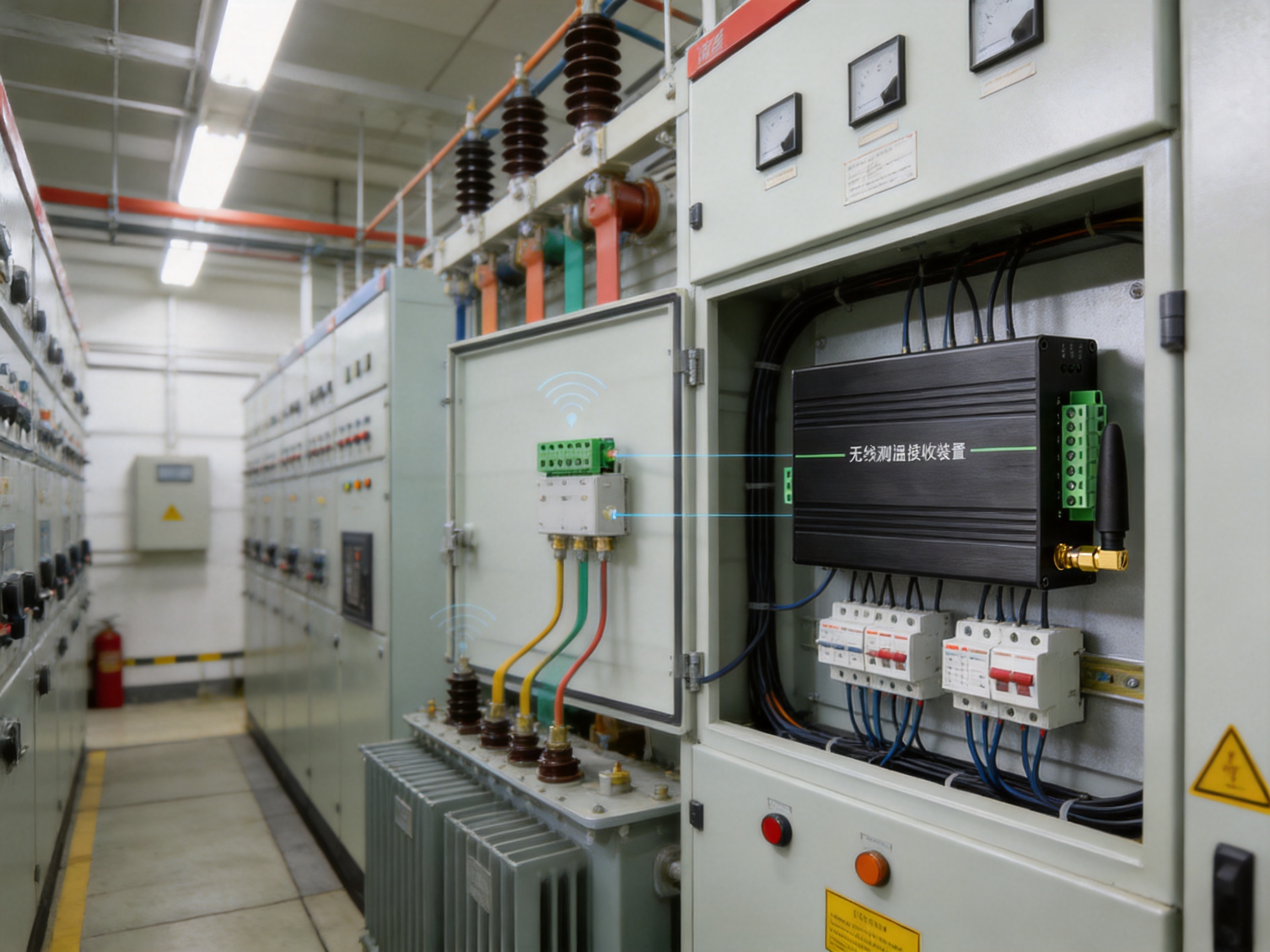
The host includes a relay dry contact rated at AC 220 V/5 A, with one set of passive normally open and normally closed contacts. A dry contact does not generate its own control voltage; instead, it switches an external circuit according to the system design. This allows the relay to be connected to an alarm indicator, contactor control circuit, building management input, or another authorized device.
A local relay output can provide an additional response path when rapid notification is important. A facility may use the contact to activate a warning lamp, audible alarm, ventilation response, equipment interlock, or digital input on a control panel. The appropriate function depends on the risk assessment and control philosophy of the site.
Relay logic should be designed carefully. Alarm thresholds, reset conditions, sensor communication loss, power failure behavior, and operator acknowledgment should be defined before commissioning. The contact rating must not be exceeded, and inductive loads should be controlled with suitable protective components. Electrical work should be performed by qualified personnel according to applicable regulations.
The relay complements rather than replaces data communication. MODBUS data can provide detailed temperature values and historical trends, while the dry contact can provide a simple hardwired indication for a critical event. This combination supports both digital monitoring and conventional control-panel alarm practices.
Industrial Environmental Performance
The stated operating ambient temperature range is -25°C to +70°C. This range supports many indoor industrial applications, electrical rooms, control cabinets, utility areas, and protected outdoor enclosures. It covers low-temperature environments as well as warm equipment rooms, provided that the actual enclosure conditions remain within the specified limits.
The specified ambient humidity is up to 95 percent. High humidity is common in industrial facilities, especially near cooling systems, process areas, water treatment equipment, storage areas, and seasonal outdoor installations. Although the specification supports humid environments, condensation control remains essential. A high relative humidity value does not mean that the product can be exposed to standing water, direct spray, or continuous condensation without suitable protection.
The stated atmospheric pressure range is 80 to 110 kPa, and the altitude rating is up to 2,500 meters. These values make the host suitable for many normal industrial and elevated-site installations. At higher altitudes, thermal management, insulation coordination, and equipment derating may need to be considered for the overall system, even when the host itself is within its specified altitude range.
Environmental performance depends on the complete installation. The control cabinet, ventilation method, cable glands, power protection, radio placement, and maintenance practices all influence long-term reliability. A properly selected host should be combined with an appropriate enclosure and a site-specific installation plan.
Advantages Compared with Conventional Monitoring Approaches
Reduced Field Cabling
The most visible advantage of a wireless system is the reduction in field wiring. Sensors can be installed at measurement points without routing an individual signal cable from every point back to a central cabinet. This can reduce installation complexity, especially where equipment is crowded, inaccessible, movable, electrically hazardous, or difficult to modify.
Scalable Network Architecture
The ability to receive data from up to 240 sensors supports a scalable design. Instead of requiring a separate receiver for every small group of sensors, a larger monitoring zone can be organized around one host. This can simplify network planning and reduce the number of devices that must be connected to the supervisory layer.
Industrial Mechanical Construction
The metal enclosure and DIN rail mounting distinguish the host from many basic wireless gateways intended primarily for office or residential environments. The product is designed for integration into industrial control cabinets, where mechanical stability, organized mounting, and service access are important.
Direct Industrial Communication
RS485 and MODBUS RTU allow the host to communicate with common automation equipment. A product that supports established industrial interfaces can be easier to integrate than a receiver that relies only on a proprietary software application or a consumer-oriented wireless protocol.
Combined Data and Alarm Connectivity
The two-channel RS485 output supports data integration, while the relay dry contact provides a local alarm or control interface. This combination gives system designers more options than a receiver offering only a wireless connection or only a serial output.
Broad Power Compatibility
The AC/DC 100–240 V input supports a wide range of installation arrangements. This can reduce the need for separate versions of the receiving host for different supply conditions and can simplify standardization across multiple projects.
Sensor Health Information
Voltage parameter support provides visibility into the condition of active sensor batteries or passive sensor supply circuits. A system that reports only temperature may leave maintenance personnel unaware of a weakening sensor power source. Temperature and voltage information together support better preventive maintenance.
Manufacturing and Product Development Strengths
The product is developed by an industrial technology company whose work centers on data sensing, intelligent connectivity, edge-layer hardware, and industrial data integration. These capabilities are relevant to a wireless temperature monitoring host because successful deployment requires more than assembling a radio module. The product must connect field sensing, wireless communication, electrical interfaces, industrial protocols, and practical installation requirements.
A strong product development process begins with application analysis. Industrial customers may require monitoring in power equipment, petroleum facilities, chemical production lines, railway infrastructure, mines, metallurgy plants, or cement factories. Each environment presents different challenges involving temperature, dust, vibration, electrical interference, access, maintenance, and communication architecture. Designing for these sectors encourages attention to practical system requirements rather than only laboratory functionality.
The company’s focus on self-developed edge-layer hardware supports closer control over the relationship between sensing devices and industrial information systems. Edge hardware is responsible for collecting data near the source, preparing it for transmission, and making it useful to higher-level software. The KS30M-LORA reflects this approach by receiving distributed sensor data and presenting it through a recognized industrial interface.
Product engineering also benefits from modular thinking. A wireless temperature host, a transmitter, a flow meter, a power line communication device, and an automatic door controller serve different applications, but they share requirements for reliable electronics, stable communication, practical enclosures, field installation, and integration with larger industrial systems. Experience across these product categories can support a broader understanding of industrial connectivity.
The stated company strengths include data sensing, intelligent connectivity, industrial data integration, equipment condition monitoring, refined energy management, and production process optimization. These areas align directly with the needs of modern smart factories. Temperature monitoring is often one part of a larger condition-monitoring strategy, and the host can act as a reliable data collection point within that strategy.
Advanced manufacturing should be understood as a complete process rather than a single machine or production step. It includes requirements definition, circuit and enclosure design, component selection, assembly control, programming, communication testing, functional verification, quality inspection, packaging, and technical support. For an industrial host, each stage contributes to final performance.
During requirements definition, the design team must translate application needs into measurable specifications. The operating temperature range, humidity, pressure, altitude, sensor capacity, wireless band, communication output, relay rating, power input, and mounting method all represent practical decisions made for industrial deployment.
During hardware development, the power supply, wireless communication section, RS485 interface, relay circuit, terminal arrangement, and enclosure must work together. The design must provide suitable separation between power and communication circuits and must support stable operation when connected to external industrial equipment.
During embedded software development, sensor identification, wireless parameter matching, register organization, temperature scaling, voltage data handling, communication timing, and relay logic must be coordinated. Consistent firmware behavior is essential when a monitoring system contains many sensor nodes.
During assembly and testing, the host should be checked for correct wiring, mechanical integrity, power response, serial communication, wireless reception, sensor identification, data accuracy, and relay operation. A structured verification process helps detect problems before the unit reaches the field.
For a product intended for industrial use, manufacturing quality also includes traceability and repeatability. The same model should provide consistent connection points, predictable communication behavior, and stable mechanical dimensions across production batches. This consistency benefits system integrators who build multiple cabinets or deploy the same monitoring architecture across several facilities.
Application in Electrical Equipment Monitoring
Electrical equipment is one of the most natural applications for wireless temperature monitoring. Connection points, busbars, cable joints, switchgear terminals, transformer interfaces, and other conductive components may develop abnormal heating when contact resistance increases or load conditions change.
A wireless sensor can be placed at a suitable measurement location, while the host receives information from many points. The monitoring system can compare similar phases, identify temperature imbalance, and generate an alarm when values exceed the configured engineering limits.
Wireless measurement can be especially helpful inside or around equipment where installing new signal cables would require extensive modification. The host can be placed in a nearby cabinet and connected to the facility’s automation or supervisory system through RS485.
Application in Petroleum and Chemical Facilities
Petroleum and chemical facilities often contain distributed equipment, process lines, pumps, motors, storage systems, and control cabinets. Temperature is relevant to equipment protection and process awareness. Wireless monitoring can reduce the need to install cables across areas where routing is difficult or where equipment access is limited.
Site-specific requirements must always be reviewed. Hazardous-area classification, intrinsic safety, enclosure requirements, radio regulations, and sensor suitability are separate considerations. The KS30M-LORA should be installed in an appropriate location and used as part of a system designed for the specific facility conditions.
Application in Railways, Mining, Metallurgy, and Cement
Railway infrastructure, mining operations, metallurgy plants, and cement facilities often combine large physical areas with demanding mechanical and environmental conditions. Equipment may be spread across substations, conveyors, crushers, kilns, motors, control rooms, and material-handling systems.
A scalable wireless host can help collect data from widely distributed temperature points while limiting the amount of new field wiring. The metal enclosure and guide rail mounting support installation in local control cabinets. RS485 communication allows the collected information to be forwarded to existing industrial monitoring equipment.
In dusty or vibrating environments, enclosure selection and installation quality are particularly important. The host should be placed in a suitable protected cabinet, while sensors should be selected and installed according to their own environmental specifications. Preventive inspection of antennas, terminals, power connections, and sensor mounting points should be included in the maintenance plan.
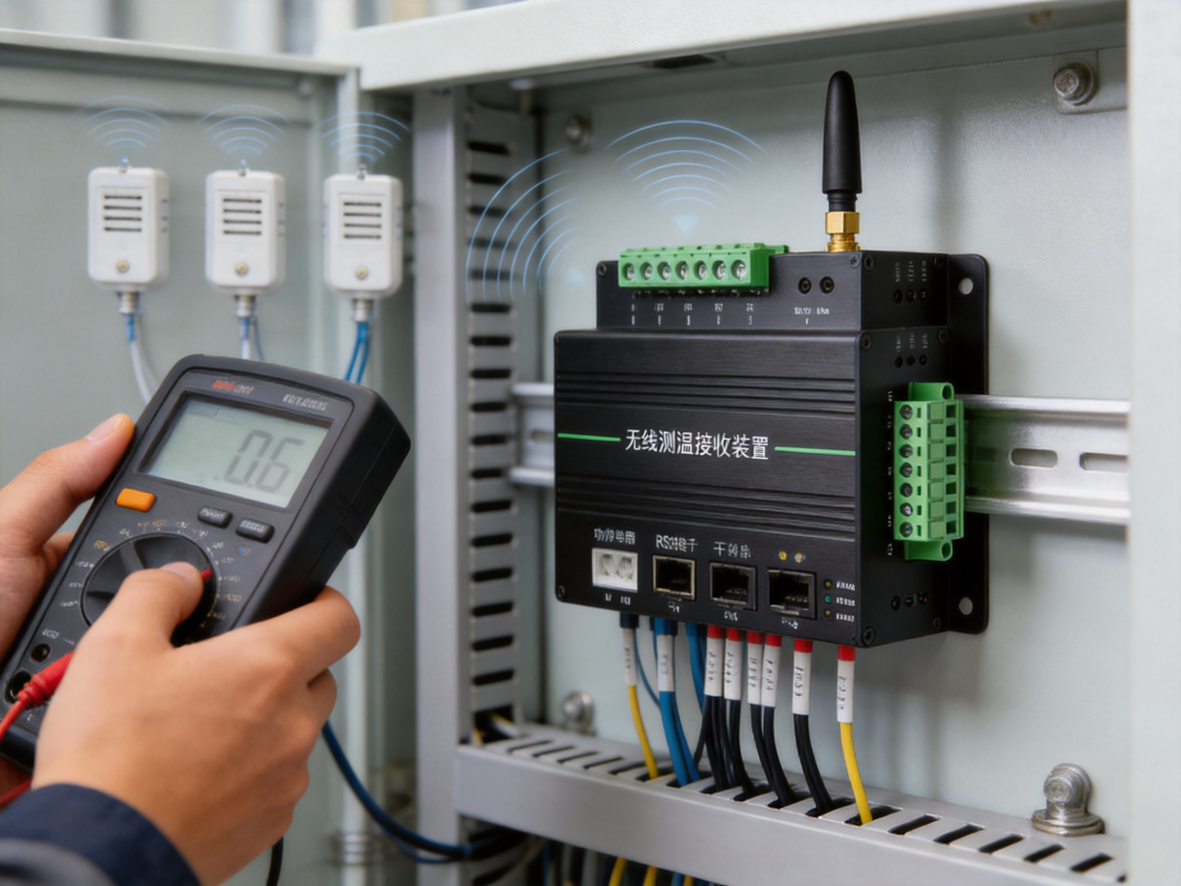
Recommended Project Design Workflow
Step One: Define the Monitoring Objective
Before selecting sensor locations, the project team should define what the system is intended to protect or improve. Objectives may include preventing overheating, tracking equipment condition, reducing manual inspections, monitoring battery status, supporting predictive maintenance, or providing a direct alarm signal.
Step Two: Create an Asset and Sensor List
Every measurement point should be associated with an asset name, physical location, sensor ID, expected operating range, alarm threshold, and maintenance responsibility. This list becomes the basis for commissioning and future troubleshooting.
Step Three: Evaluate Radio Conditions
The team should review cabinet construction, distance, obstacles, antenna orientation, neighboring radio equipment, and possible sources of interference. A practical field test can confirm whether the proposed sensor and host positions provide stable communication.
Step Four: Plan Power and Communication Wiring
The host requires a suitable AC/DC 100–240 V supply and an RS485 connection to the upper-level system. Power protection, cable separation, grounding, termination, and access for maintenance should be included in the cabinet design.
Step Five: Configure IDs and Parameters
Sensor IDs and wireless matching parameters should be configured systematically. A documented numbering plan avoids duplication and makes the MODBUS data easier to interpret. The installer should confirm that every received value matches the correct physical sensor.
Step Six: Test Normal and Alarm Conditions
Commissioning should include normal temperature readings, voltage data, communication polling, relay operation, power cycling, and loss-of-communication checks where applicable. The purpose is to verify the complete chain from sensor to host to monitoring platform.
Step Seven: Establish Maintenance Procedures
Maintenance procedures should include inspection of sensor attachment, battery or supply voltage, wireless communication status, host power, RS485 wiring, enclosure condition, and alarm response. Historical temperature trends should be reviewed periodically to identify changes that may not yet have reached an alarm threshold.
Maintenance and Reliability Practices
Industrial wireless monitoring systems are most effective when they are treated as operational assets rather than installed and forgotten. The host should be included in routine cabinet inspections. Maintenance personnel should check for loose terminals, unusual heating, contamination, moisture, mechanical damage, and signs of cable stress.
Sensor maintenance should be based on sensor type. Active sensors may require battery replacement according to voltage status and operating conditions. Passive sensors should be checked for the integrity of their power and measurement connections. The voltage parameter can support this maintenance process, but it should be interpreted according to the relevant sensor design.
Communication records should be reviewed when available. Repeated missing data, abnormal response times, or inconsistent values may indicate a weak radio path, antenna issue, power problem, sensor failure, or incorrect parameter configuration. Troubleshooting is easier when the physical sensor list and MODBUS register map are up to date.
Alarm thresholds should be reviewed after the facility has accumulated sufficient operating history. Initial thresholds may be based on equipment specifications and engineering judgment. Later adjustments can account for seasonal ambient changes, normal load variation, and the difference between a temporary peak and a sustained abnormal trend.
Integration with Smart Factory Systems
Temperature monitoring becomes more valuable when integrated with a larger industrial information architecture. The KS30M-LORA can provide measurement data to a PLC, industrial gateway, SCADA platform, or other MODBUS RTU master. From there, data may be used for dashboards, alarms, trend analysis, maintenance records, energy analysis, and production decision-making.
At the edge layer, the host gathers data close to the equipment. This reduces the need for every sensor to communicate directly with a remote server and provides a structured local interface. The larger system can then combine temperature data with current, voltage, pressure, flow, vibration, production, or energy information.
Such integration supports the development of smart factories. A temperature increase can be correlated with equipment load, operating time, process conditions, and maintenance history. Over time, these relationships can help companies move from reactive repairs to condition-based maintenance and more efficient production management.
Selection Considerations for Buyers and Integrators
When comparing wireless temperature monitoring hosts, buyers should look beyond wireless range claims and consider the complete industrial architecture. Important questions include the number of supported sensors, the wireless frequency, the enclosure design, the installation method, communication interfaces, protocol support, relay options, operating environment, power input, and the availability of technical documentation.
The KS30M-LORA is particularly suitable when a project requires a metal, DIN rail-mounted receiving host with a relatively high sensor capacity, RS485 integration, standard MODBUS RTU communication, and a relay dry contact. These features can be more valuable than a basic receiver’s lower initial cost when the system must operate as part of a larger industrial control environment.
Buyers should also evaluate the supplier’s ability to support application engineering. A successful deployment may require assistance with sensor selection, wireless planning, register mapping, ID organization, cabinet installation, and commissioning. A supplier with experience in industrial communication and data integration can provide more useful support than a vendor focused only on individual electronic modules.
Customization discussions should clearly define the required frequency, sensor types, communication structure, relay behavior, power arrangement, enclosure requirements, and software or protocol expectations. Any project-specific change should be validated before mass deployment.
Q&A
What is the KS30M-LORA?
It is an industrial wireless temperature monitoring host with a metal enclosure and guide rail mounting. It receives data from wireless temperature sensors and transfers the information through RS485 communication.
How many sensors can the host receive?
The stated maximum is 240 sensors. The practical number used in a project should also consider wireless conditions, sensor models, polling arrangements, installation layout, and system documentation.
What wireless frequency does it use?
The host uses a Sub-GHz wireless frequency band, with 433 MHz specified as the default. The final configuration should comply with applicable local requirements and the project’s radio plan.
What communication protocol is supported?
The default communication protocol is standard MODBUS RTU over RS485. The default serial settings are 9,600 bps, 8 data bits, 1 stop bit, and no parity.
Does the host provide more than one RS485 output?
Yes. The technical information specifies two-channel RS485 communication output. The channels should be assigned according to the project’s control and monitoring architecture.
What temperature information is available?
Temperature data is provided as 16-bit data with the most significant digit first. The stated resolution is 0.1°C, and the stated error is ±1°C.
Can the host report sensor battery condition?
It can provide a voltage parameter. For an active sensor, the value represents battery voltage. For a passive sensor, it represents the voltage after rectification and regulation. The interpretation should follow the relevant sensor documentation.
Does it include an alarm output?
Yes. The host includes one set of passive normally open and normally closed relay contacts rated at AC 220 V/5 A. The relay should be connected and protected according to the electrical design and load requirements.
Where can the host be installed?
It is designed for guide rail installation and also supports screw installation. Typical locations include control cabinets, distribution panels, electrical rooms, and protected industrial enclosures.
What is the operating temperature range?
The stated ambient operating temperature range is -25°C to +70°C.
Can it be used in a humid environment?
The stated ambient humidity is up to 95 percent. The installation must still protect the host from direct water, unsuitable condensation, and environmental conditions beyond the product specification.
Is the host suitable for a smart factory system?
Yes. Its wireless sensing function, RS485 interface, MODBUS RTU protocol, sensor capacity, and relay output make it suitable for integration into equipment condition monitoring and industrial data systems.
Does wireless communication eliminate the need for site planning?
No. Radio performance depends on distance, metal structures, cabinet construction, interference, antenna location, and other site conditions. A field evaluation and structured commissioning process are recommended.
What makes this host different from a basic wireless receiver?
Its industrial-oriented combination of a metal enclosure, guide rail installation, up to 240 sensor capacity, two-channel RS485 output, MODBUS RTU support, wide AC/DC input, voltage data, and relay dry contact provides broader integration options than a receiver intended only for simple local display.
Conclusion
The KS30M-LORA is designed to serve as the central communication and data collection unit in an industrial wireless temperature monitoring system. Its role is to receive information from distributed temperature sensors and connect that information to automation, monitoring, and alarm systems.
The product combines features that matter in industrial deployment: a metal enclosure, DIN rail and screw installation, AC/DC 100–240 V power input, Sub-GHz wireless communication, support for up to 240 sensors, two-channel RS485 output, MODBUS RTU communication, sensor ID configuration, temperature and voltage data, and a relay dry contact.
Compared with basic wireless receivers or isolated measurement devices, this combination supports a more complete monitoring architecture. It can reduce field wiring, simplify integration, provide a scalable sensor network, and supply both detailed digital data and a conventional relay alarm path.
The company’s broader strengths in data sensing, intelligent connectivity, edge-layer hardware, industrial communication, and data integration support the product’s position within smart factory applications. Through disciplined product development, application-oriented engineering, manufacturing control, and industrial system experience, the host can become part of a practical condition-monitoring strategy.
For best results, the product should be selected and installed as part of a complete engineering plan. Sensor placement, radio conditions, power protection, RS485 wiring, register mapping, alarm logic, environmental protection, and maintenance procedures all contribute to system performance. When these factors are addressed, a wireless temperature monitoring host can help industrial operators identify abnormal conditions earlier, improve maintenance planning, and build a stronger foundation for connected and sustainable production.
References
1. Product technical information for the KS30M-LORA wireless temperature monitoring host, including environmental specifications, communication parameters, sensor capacity, installation method, and relay output.
2. Industrial automation design practices for RS485 serial communication and MODBUS RTU network integration.
3. General principles of equipment condition monitoring and temperature-based preventive maintenance.
4. Industrial control cabinet design practices covering DIN rail installation, power protection, signal separation, grounding, and maintenance access.
5. Smart factory architecture principles for edge-layer data sensing, industrial connectivity, equipment monitoring, and production process optimization.
6. General engineering guidance for Sub-GHz wireless deployment in industrial environments, including radio planning, antenna positioning, obstacle assessment, and commissioning.