

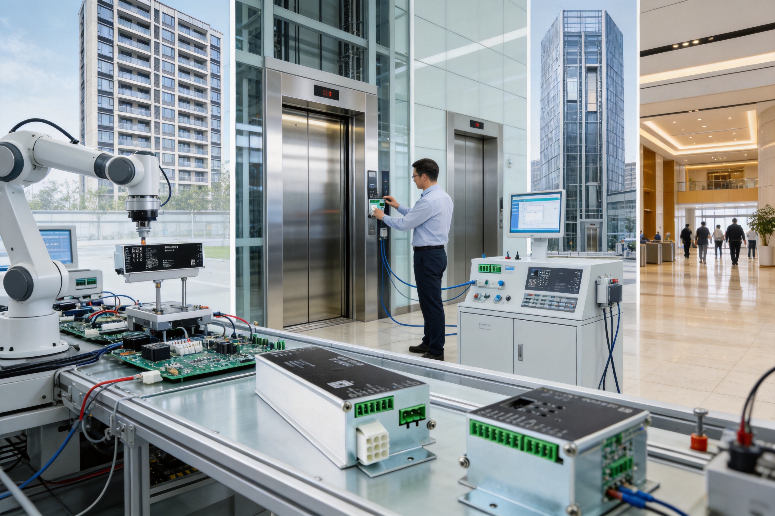
Elevator doors are among the most frequently operated moving systems in a building. In residential towers, hospitals, hotels, transport facilities, office buildings, and industrial sites, a door operator may open and close hundreds of times each day. Every cycle requires accurate motion control, dependable positioning, controlled acceleration and deceleration, obstruction detection, and reliable communication with the elevator system. A poorly matched controller can lead to noise, vibration, door impact, nuisance faults, premature motor wear, and unnecessary maintenance.
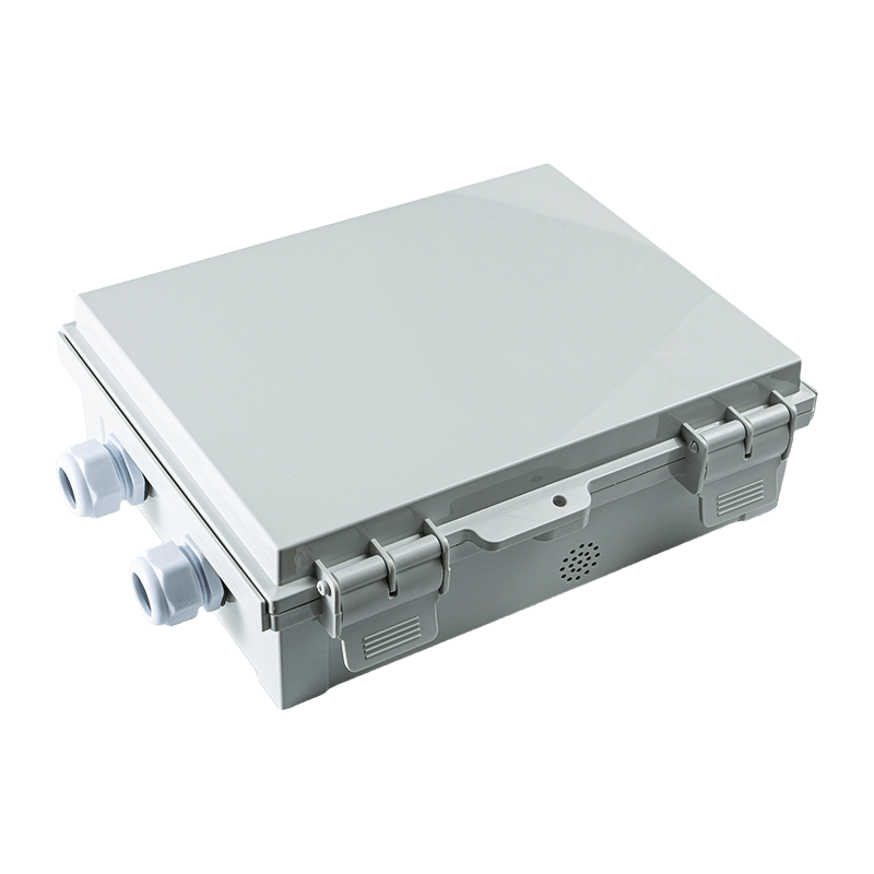
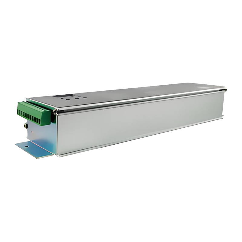
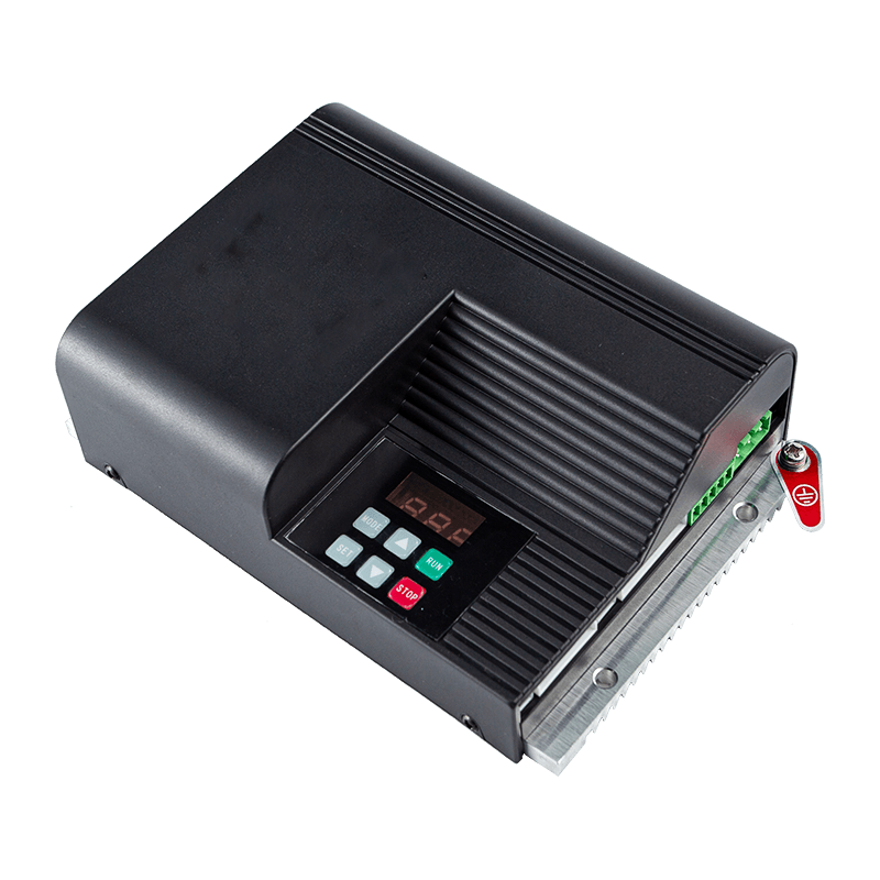
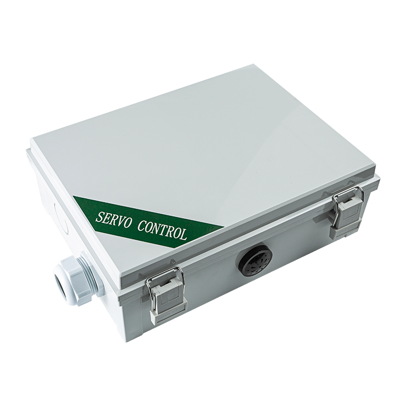
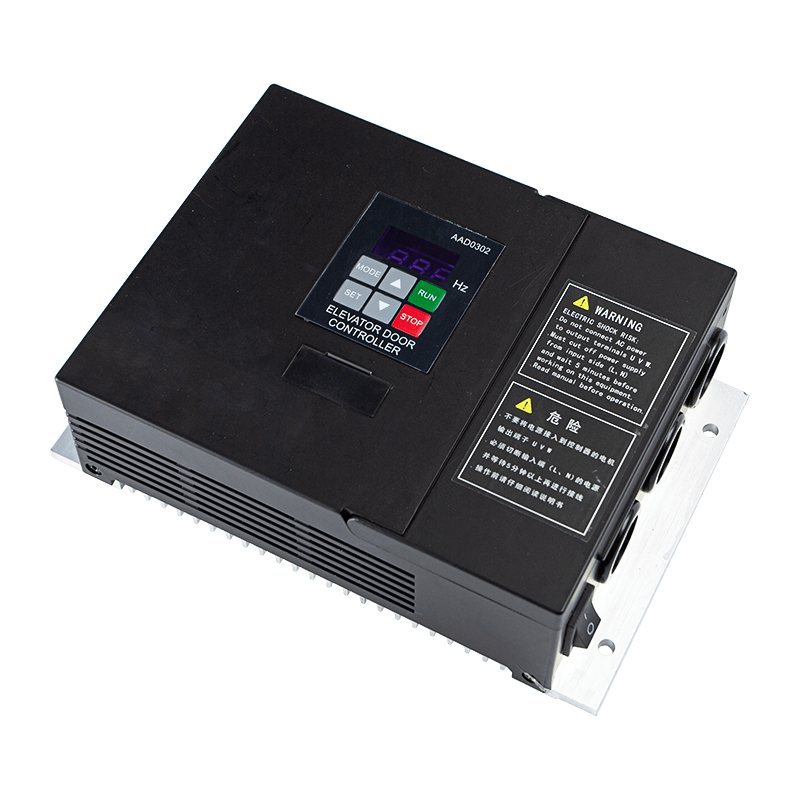
The AIG-150E-02 is a high-performance elevator door controller designed to address these requirements through coordinated motor control, adjustable operating parameters, integrated safety functions, diagnostic feedback, and flexible signal interfaces. It is primarily intended for sliding elevator and automatic door applications, with support for brushless DC motor configurations and broader compatibility with general synchronous and asynchronous elevator door operators according to the product performance specifications.
Developed by ASY Electronics (JiaXing) Co., Ltd., the controller reflects the company’s wider focus on intelligent connectivity, equipment condition monitoring, industrial control, and edge-layer hardware. Rather than functioning as a simple motor switch, the AIG-150E-02 acts as a configurable motion-control platform. It allows installers and technicians to adapt door behavior to different mechanical structures, motor characteristics, safety requirements, and building operating conditions.
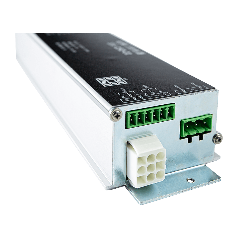
DC Brushless Elevator Door Controller
Why Elevator Door Control Requires More Than Basic Motor Switching
An elevator door must move smoothly over a defined travel distance while responding to multiple external commands. The controller must interpret opening and closing signals, manage the motor through different speed phases, detect the end positions, protect the motor, and react quickly if an obstacle appears in the door path. These tasks must be coordinated without creating unnecessary stress on the drive mechanism.
A basic relay-based system may provide only on-and-off control. Such an approach can be acceptable for simple gates, but elevator doors require more refined behavior. At the beginning of movement, the controller must provide sufficient starting torque to overcome static resistance. During travel, it must maintain an appropriate speed. Near the fully open or fully closed position, it must reduce speed and control torque so that the door arrives gently rather than striking the mechanical stop.
The AIG-150E-02 uses configurable parameters for these stages. Opening speed, closing speed, delay before automatic closing, anti-pinch torque, holding torque, and other operating values can be adjusted according to the door design. Technician-level settings can also address motor pole pairs, reduction ratios, and speed-loop proportional and integral parameters. This makes the controller suitable for systems where a fixed, non-adjustable control profile would be inadequate.
Door control also involves safety and serviceability. If the door encounters resistance, the system needs to recognize the abnormal condition and take appropriate action. If an encoder or Hall sensor fails, the technician needs a clear fault indication rather than an unexplained failure to operate. If a system requires commissioning after installation, the service team needs access to operating states, parameter settings, and recovery functions.
These needs explain why the AIG-150E-02 combines motion control, digital status display, protective functions, input and relay interfaces, and serial communication in one controller. Its value lies not only in its electrical output, but also in the way it integrates control, monitoring, adjustment, and troubleshooting.
Product Overview
The AIG-150E-02 is a controller for lift and sliding-door applications. The product description identifies it as a brushless DC controller designed for lift doors, while its published performance parameters state that it can be used with general synchronous elevator door operators and general asynchronous elevator door operators. This combination gives the product a wider application perspective than a controller limited to one motor technology.
The unit operates from a single-phase AC supply within a rated input range of 176–264 VAC at 50/60 Hz. This range covers common 220 V electrical systems while allowing reasonable tolerance around the nominal voltage. The controller supports a maximum output current of 3 A and a maximum output power of 500 W, subject to the characteristics of the selected motor and the actual application.
Its input signals include open, close, anti-pinch or fire protection, arrival, and motor thermal protection. Relay outputs provide open-position reached, close-position reached, and fault-alarm signals. A serial communication port can connect to an external touchscreen or debugging panel, giving technicians another method for commissioning and service.
Item | Specification or Function |
Model | AIG-150E-02 |
Primary application | Sliding elevator doors and automatic door operators |
Input voltage | 176–264 VAC |
Input frequency | 50/60 Hz |
Motor output capability | Maximum current of 3 A and maximum power of 500 W |
Motor applications | Brushless DC, general synchronous, and general asynchronous configurations as applicable to the system design |
Control inputs | Open, close, anti-pinch/fire protection, arrival, and motor thermal protection |
Relay outputs | Open position, close position, and fault alarm |
Communication | One serial communication port for an external touchscreen or debugging panel |
Display | Digital tube display for operating status and fault information |
The controller is also associated with compatible brushless DC motor configurations, including the MT02-WS-100W model described in the product information. The documentation also references an MT01-YC-43W motor rated for operation from -20°C to 50°C. Actual compatibility must always be confirmed against the motor nameplate, mechanical load, wiring arrangement, and final application requirements.
Controlled Motion for Smoother Door Operation
A major advantage of the AIG-150E-02 is its ability to manage different phases of door movement rather than applying a uniform command throughout the entire cycle. A typical door cycle may include initial starting, acceleration, normal travel, deceleration, final positioning, and holding. Each phase has a different control objective.
During starting, the motor must overcome static friction and the inertia of the door panels. Insufficient starting torque can produce hesitation, repeated restart attempts, or a failure to move under unfavorable conditions. Excessive starting torque, however, may create a sudden movement and unnecessary mechanical shock. The controller’s starting-torque settings allow the commissioning technician to seek a suitable balance.
During normal travel, the goal is consistent movement at a selected opening or closing speed. The speed should be appropriate for the door weight, travel length, mechanical transmission, and safety requirements. Adjustable opening and closing speed parameters allow the operator to be adapted to different installations instead of forcing every door to use the same profile.
At the end of travel, deceleration becomes particularly important. A door that approaches the final position too quickly can cause impact, noise, vibration, and stress on belts, rollers, guides, couplings, and structural components. The technician parameters for speed-loop control, including KP and KI settings, provide deeper adjustment of acceleration and deceleration behavior. These settings can help achieve a more stable response when the motor and mechanical system have different dynamic characteristics.
Once the door reaches its intended position, holding torque can help maintain the position and prevent unwanted movement. The appropriate holding value depends on the door mechanism and the system design. The controller allows this phase to be configured instead of relying on a single fixed motor behavior.
This multi-phase approach is one of the product’s key advantages over simpler competing controllers. A basic controller may operate a motor, but it may not provide the same level of adjustment for starting torque, anti-pinch response, speed-loop behavior, and holding torque. The result is greater flexibility during commissioning and more opportunity to optimize the door for smooth, quiet, and repeatable operation.
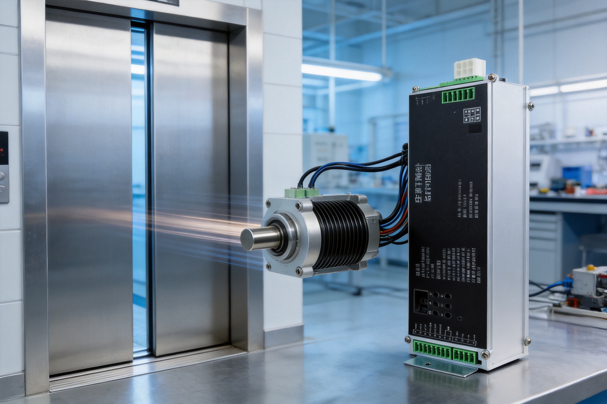
Adjustable Parameters for Different Door Designs
Elevator doors vary significantly. A small residential lift, a hospital elevator, a freight-oriented installation, and a high-traffic commercial elevator may use different door weights, travel distances, guide systems, motor ratings, reduction mechanisms, and operating schedules. Even two doors with similar dimensions may behave differently because of variations in alignment, friction, belt tension, or panel construction.
The AIG-150E-02 divides its adjustment functions into user parameters and technician parameters. This separation is useful because it allows routine operating values to be adjusted without exposing every advanced motor-control setting to general users.
User Parameters
User parameters in the P-series can be used to adjust practical operating behavior. These include opening speed, closing speed, automatic closing delay, and anti-pinch torque. Such settings are important during commissioning and may also be reviewed when the building’s operational requirements change.
For example, a hospital environment may require a different closing profile from a low-traffic private building. A higher-traffic installation may benefit from a carefully selected automatic closing delay that reduces unnecessary waiting while still allowing passengers sufficient time to enter or exit. Anti-pinch settings can also be adapted to the door’s mechanical characteristics and the required sensitivity of obstruction response.
Technician Parameters
Technician parameters in the F-series provide deeper control of the motor and transmission system. These settings include motor pole pairs, reduction ratios, and advanced KP/KI values for the speed ring. Correct configuration helps the controller interpret the motor correctly and coordinate its electrical output with the mechanical reduction system.
Access to these settings is valuable when replacing a motor, adapting the controller to a different door operator, or correcting a motion profile that cannot be optimized through basic speed settings alone. It also supports service teams that need to diagnose whether an issue is caused by motor configuration, mechanical resistance, feedback signals, or control-loop tuning.
The availability of two parameter levels provides a practical compromise between usability and technical depth. Operators can access necessary settings, while qualified technicians retain the tools needed for more advanced adjustment. This structure can reduce accidental changes to critical parameters and make maintenance procedures more organized.
Digital Status Display and Commissioning Support
Commissioning an elevator door controller is more efficient when the installer can see the controller’s current state directly. The AIG-150E-02 uses a digital tube display to provide real-time operating feedback. The product information references status indications such as automatic door-width measurement, normal opening, and normal closing.
During installation, the display can assist the technician in confirming whether the controller has entered the expected operating stage. A status indication associated with automatic width measurement can help identify whether the system is learning or verifying the door travel. Opening and closing indications can help distinguish an input-command issue from a motor or mechanical issue.
Visible status information is especially useful when the controller is installed inside a cabinet or equipment compartment where connecting a separate diagnostic device for every basic check would be inconvenient. It can shorten the initial inspection process and help technicians determine whether the next step should involve wiring, parameters, motor feedback, or mechanical adjustment.
The serial communication port extends this service capability. An external touchscreen or debugging panel can provide a more detailed interface when required. This is useful for manufacturers, integrators, and maintenance organizations that need to review parameters, inspect system behavior, or conduct structured troubleshooting.
Integrated Safety Functions
Door safety is a central requirement in any elevator installation. The controller includes an anti-pinch or fire-protection input, blocking detection, motor thermal protection input, and fault monitoring. These functions contribute to a layered safety strategy in which the controller responds to both external safety signals and internal operating abnormalities.
Blocking Detection
Blocking detection is designed to identify when the door’s path is obstructed or when the motor encounters abnormal resistance. Its sensitivity can be adjusted, allowing the system to respond according to the mechanical design and expected operating conditions. Proper adjustment is important: a setting that is too insensitive may delay the response to an obstruction, while one that is too sensitive may cause nuisance reversals or interruptions during normal operation.
Blocking detection should not be treated as a substitute for the complete elevator safety system. It is one control-layer function that must be integrated with the elevator’s door sensors, safety circuits, mechanical design, and applicable installation requirements. Nevertheless, the presence of adjustable detection gives technicians a useful tool for balancing responsiveness and stable operation.
Anti-Pinch and Fire-Protection Input
The anti-pinch or fire-protection input allows external safety logic to influence door operation. The exact signal behavior depends on the elevator system design and wiring method. In an integrated installation, this input can be connected to the appropriate safety or emergency control circuit so that the door controller follows the required system command.
Motor Thermal Protection
Motor thermal protection input provides another layer of protection against overheating. Excessive load, repeated operation, poor mechanical alignment, or abnormal friction can increase motor temperature. A thermal protection signal allows the system to detect the condition and prevent continued operation that could damage the motor or drive components.
Fault Alarm Output
The relay fault-alarm output allows an external system to receive information about controller abnormalities. This can support elevator control logic, building maintenance procedures, or a local alarm arrangement. Open-position and close-position relay outputs can also provide clear confirmation that the door has reached its intended position.
Diagnostic Capability and Fault Identification
Unclear fault behavior increases maintenance time. When a door fails, technicians need to know whether the problem is related to feedback, power, motor loading, wiring, or configuration. The AIG-150E-02 includes a fault-diagnosis system with codes for specific conditions.
The published examples include encoder or Hall failure identified as E02, overvoltage identified as E05, and motor overload identified as E18. These codes do not eliminate the need for professional testing, but they provide a structured starting point. A technician can compare the displayed code with the wiring, motor feedback, supply voltage, mechanical condition, and parameter settings.
Encoder or Hall-related faults may point toward damaged cables, incorrect connections, feedback-device problems, electrical interference, or an incompatible motor configuration. An overvoltage fault may require inspection of the supply, braking behavior, wiring, or system conditions. A motor overload indication may lead to checks of door alignment, guide friction, belt tension, panel interference, starting torque, and motor sizing.
Diagnostic codes can also improve communication between equipment operators and service providers. Instead of reporting only that “the door does not work,” an operator can report the code shown on the controller. This makes service preparation more efficient and can reduce unnecessary replacement of functioning components.
The controller’s accumulated working-hour tracking adds another maintenance-oriented function. Operating-hour information can help organizations plan inspections, compare usage among installations, and establish maintenance intervals based on actual service activity rather than calendar time alone.
Electrical Compatibility and Interface Design
The AIG-150E-02 is designed for 176–264 VAC, 50/60 Hz single-phase input. This range is suitable for nominal 220 V systems and offers a practical operating window for common industrial and commercial electrical environments. Installation should still include appropriate protection, grounding, isolation, and compliance checks for the local electrical system.
The maximum output current is specified as 3 A, and maximum output power is specified as 500 W. These values provide a useful framework for motor selection, but they should not be interpreted as permission to connect any motor below the nominal power limit without further verification. Motor voltage, feedback type, pole-pair configuration, reduction ratio, starting characteristics, duty cycle, and mechanical load must all be considered.
The control inputs are designed to receive the main commands and protection signals required by a door operator. Open and close commands determine the requested direction. The anti-pinch or fire-protection input supports safety-related system behavior. The arrival input can be used within the application’s position or arrival logic, while the motor thermal protection input allows temperature-related protection to be incorporated.
Relay outputs provide straightforward status signaling. Open-position and close-position outputs can be connected to external control circuits, while the fault-alarm output can transmit an abnormal condition to a supervisory or elevator controller. The serial port provides a separate path for a touchscreen or debugging panel, supporting service and commissioning without replacing the main control interface.
This combination of discrete inputs, relay outputs, and serial communication gives the controller an advantage over products that provide only motor terminals and a limited command interface. It can participate in a broader control architecture while still offering local status and adjustment functions.
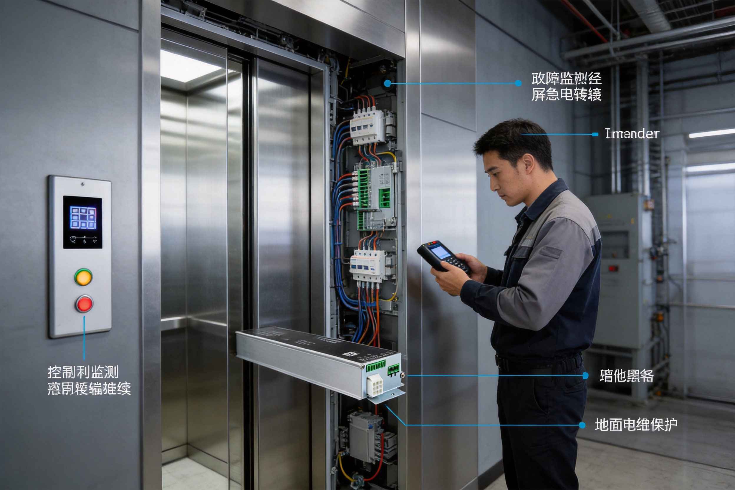
Motor and Application Flexibility
The product is specifically described as a brushless DC controller for lift doors and is associated with the MT02-WS-100W brushless DC motor. At the same time, its performance information states that it supports high-voltage servo motors or high-voltage asynchronous motors and is suitable for general synchronous and asynchronous elevator door operators.
This broader application description makes the AIG-150E-02 relevant to different door-control projects, but compatibility must be verified before installation. The controller should be matched with the motor technology, feedback arrangement, voltage, current, mechanical reduction, door mass, and travel requirements. A qualified engineer or installer should confirm all motor and wiring details using the applicable technical documentation.
Motor flexibility can be an important advantage in replacement and modernization projects. Building owners may not want to replace the entire door mechanism when only the controller has become obsolete. A controller that can be configured for more than one motor arrangement may provide integrators with additional options, subject to electrical and mechanical compatibility.
The product information also references motor operation in temperatures from -20°C to 50°C for a compatible motor such as the MT01-YC-43W. This indicates suitability for a range of indoor and semi-controlled environments, although the complete system’s temperature rating depends on the controller enclosure, ventilation, humidity, installation location, and other components.
Operating Modes for Practical Service and Testing
The AIG-150E-02 supports primary-secondary models, emergency battery modes, and an aging demonstration mode. These operating options can be valuable for equipment manufacturers and service teams.
A primary-secondary configuration may be used where the door system has coordinated control relationships or where one control arrangement works with another defined unit. The exact wiring and operating sequence must follow the system design. This mode can be relevant to projects requiring coordinated equipment behavior rather than an isolated door controller.
An emergency battery mode supports applications where door operation must be considered during a power interruption or emergency condition. The details of battery capacity, operating sequence, safety behavior, and permitted movement depend on the final elevator system. The controller should be integrated with the approved emergency power and safety architecture.
An aging demonstration mode can assist with testing and endurance evaluation. Manufacturers and integrators may use a controlled demonstration cycle to observe repeated operation, verify parameter stability, and identify mechanical problems before the equipment is placed into service. Aging tests can be particularly useful for detecting issues such as excessive friction, loose connections, inadequate cooling, or unsuitable speed and torque settings.
Manufacturing and Engineering Strengths
The performance of an industrial controller depends on more than its circuit design. Consistent production, organized configuration management, reliable testing, and traceable technical support are also important. ASY Electronics describes itself as a high-tech enterprise focused on smart factories, data sensing, intelligent connectivity, industrial data integration, equipment condition monitoring, energy management, and production-process optimization.
This business focus is relevant to the AIG-150E-02 because an elevator door controller is both an electronic control device and an edge-layer industrial product. It must interact with sensors, motors, safety signals, and mechanical equipment. A manufacturer experienced in connecting physical equipment with digital control systems is positioned to understand the practical requirements of such products.
The company’s product portfolio includes broadband power line carriers, wireless temperature monitoring systems, transmitters, thermal gas mass flow meters, and automatic door controllers. This range indicates experience across communication, sensing, measurement, and control. Although each product category has different technical requirements, they share common engineering themes: signal integrity, reliable field operation, industrial environmental considerations, and the conversion of physical conditions into usable control or monitoring information.
Edge-Layer Product Development
Self-developed edge-layer hardware can support closer coordination between sensors, actuators, and higher-level systems. In the case of a door controller, the edge device is responsible for immediate decisions such as motor control, obstruction response, position status, and fault indication. These decisions need to occur locally and consistently, without depending on a remote server or external network.
The AIG-150E-02’s local display, configurable control parameters, fault codes, relay outputs, and serial interface are consistent with this edge-control approach. The controller can carry out essential motion and safety-related functions locally while also providing information to connected equipment and service tools.
Industrial Data Integration Perspective
Industrial data integration is valuable when equipment status must be understood over time. Working-hour accumulation, fault information, position outputs, and operating states can support maintenance records and system-level monitoring. The controller is not presented as a complete cloud platform, but its interfaces create opportunities for integration with external control and diagnostic systems.
For equipment builders, this can simplify the design of a larger door-operator solution. For building operators, it can support clearer maintenance workflows. For service providers, it can make fault reporting and parameter management more systematic.
Manufacturing Process Considerations
Reliable controller manufacturing generally requires disciplined handling of electronic components, printed-circuit-board assembly, firmware loading, parameter verification, functional testing, input and output inspection, and final product quality checks. The specific production equipment, factory certifications, and internal test procedures for an individual order should be confirmed directly with the manufacturer.
From a product-evaluation perspective, the AIG-150E-02 demonstrates several characteristics associated with a mature industrial-control development process: defined electrical ratings, organized user and technician parameter groups, named fault codes, multiple protection inputs, relay status outputs, communication capability, and application-specific recovery functions. These features suggest that the product is designed for repeatable deployment and service rather than one-off experimental use.
For original equipment manufacturers and system integrators, manufacturing strength also includes the ability to communicate technical requirements clearly. Motor compatibility, door type, wiring method, environmental conditions, and parameter needs should be reviewed before production and installation. A manufacturer that can support this engineering exchange can reduce the risk of applying a standard product to an unsuitable door system.
Advantages Compared with Simpler Competing Controllers
The AIG-150E-02 should be compared with competing products according to actual application requirements rather than price alone. Its principal advantages are related to control depth, safety integration, diagnostics, application flexibility, and service support.
1. More Detailed Motion Adjustment
Many basic controllers offer only a small number of speed settings. The AIG-150E-02 provides user-level speed and delay adjustments together with technician-level motor and speed-loop parameters. This creates more opportunities to tune the system for different door masses, mechanisms, and operating conditions.
2. Wider Control Architecture
The combination of command inputs, protection inputs, relay outputs, and serial communication gives the product a broader interface structure than a controller that only accepts open and close commands. It can exchange meaningful status and alarm information with other parts of an elevator or building-control system.
3. Local Diagnostics
Digital status indications and named fault codes help technicians move from symptom identification to targeted inspection. This can reduce troubleshooting time and limit unnecessary replacement of motors, sensors, or control boards.
4. Configurable Obstruction Response
Adjustable blocking detection and anti-pinch torque allow the system to be adapted to the door’s mechanical behavior. A fixed response profile may be less suitable when installations have different friction levels, weights, or operating requirements.
5. Support for Modernization
Compatibility with brushless DC configurations and the stated support for synchronous and asynchronous elevator door operators can provide options for retrofit and modernization work. Compatibility verification remains essential, but the product is not restricted to a single narrowly defined door concept.
6. Service-Oriented Functions
Accumulated working hours, parameter recovery, aging demonstration, and an external debugging-panel interface are useful features for installation teams and maintenance organizations. These functions can support commissioning, endurance testing, restoration of defined settings, and long-term service planning.
Installation and Commissioning Guidance
The controller requires professional installation. Before connection, the installer should verify the supply voltage, motor rating, feedback type, terminal definitions, grounding arrangement, input logic, and external safety circuits. The product information specifically emphasizes strict grounding of the earth wire and the use of shielded encoder cables to reduce interference.
Grounding is important for personnel safety, electromagnetic compatibility, and stable operation. The earth conductor should be connected according to applicable electrical standards and the installation design. It should not be omitted or substituted with an unsuitable signal connection.
Shielded cables are especially important for encoder and Hall feedback because low-level feedback signals can be affected by electrical noise from motor switching, power wiring, relays, and other equipment. Cable routing, shield termination, separation from high-power conductors, and connector quality should all be considered during installation.
After wiring, the installer should verify that the door moves in the correct direction and that the open and close commands correspond to the intended movement. The system should then be configured for the selected motor, pole pairs, reduction ratio, and other required parameters. Automatic door-width measurement or related learning procedures should be completed according to the technical instructions for the specific door type.
Opening and closing speeds should be adjusted conservatively at first. The technician can observe starting, acceleration, normal travel, deceleration, and final positioning. If the door hesitates, impacts the stop, reverses unnecessarily, or fails to hold position, the cause may involve mechanical alignment, torque settings, speed-loop tuning, feedback wiring, or motor selection.
Safety functions should be tested under controlled conditions. Obstruction detection, anti-pinch behavior, emergency or fire-protection inputs, thermal protection, position outputs, and fault alarms should be checked as part of the complete elevator system. Testing should be performed by qualified personnel using procedures appropriate to the applicable regulations and equipment design.
Maintenance and Lifecycle Value
Door operators are exposed to repeated mechanical movement, making preventive maintenance important. The controller’s working-hour tracking can support a usage-based maintenance approach. Service teams can use accumulated hours alongside door-cycle records, inspection results, and fault history to plan maintenance more effectively.
Maintenance should include inspection of door guides, rollers, belts, couplings, mechanical stops, fasteners, motor mounting, wiring, connectors, and protective earth connections. Electrical diagnosis alone cannot correct a door that is mechanically misaligned or obstructed. Likewise, a mechanical repair may not resolve a problem caused by an incorrect motor parameter or damaged feedback cable.
When a system requires restoration, the parameter-recovery function can help return the controller to defined factory settings for a specific gate type. Before recovery, technicians should record current parameters and confirm that the selected recovery profile matches the door configuration. A factory reset is not a replacement for re-commissioning; travel learning, speed verification, safety testing, and motor compatibility checks may still be required.
Long-term value comes from the combination of reliable control and maintainability. A controller that is easy to diagnose and configure may reduce downtime even when occasional component faults occur. Clear fault codes and accessible settings can also make training easier for service technicians who support multiple installations.
Applications Across Building and Industrial Environments
The primary application is elevator door control, including general synchronous and asynchronous elevator door operators. The controller’s sliding-door orientation also makes it relevant to automatic sliding-door systems that share comparable motor-control and safety requirements, provided the final application is technically suitable.
In medical facilities, smooth movement, controlled closing, and dependable anti-pinch behavior are important. The product information references configurations for medical gates, including encoder-synchronous and DC brushless versions. Such applications may require careful adjustment of speed, delay, torque, and safety-input behavior to match the facility’s operational needs.
In office buildings and residential towers, low noise and consistent operation are major priorities. Proper acceleration and deceleration tuning can reduce impact and vibration, while position feedback and relay outputs can improve coordination with the elevator controller.
In hotels, transport facilities, and other high-traffic buildings, repeated cycling places greater emphasis on thermal management, mechanical maintenance, and fault diagnosis. Working-hour tracking and aging demonstration functions can be useful during service planning and equipment evaluation.
Industrial or specialized environments may have wider temperature variation, electrical noise, or more demanding maintenance requirements. The system should be installed in a suitable enclosure and evaluated against the actual environmental conditions. The referenced -20°C to 50°C rating applies to the compatible motor noted in the product information and should not automatically be assumed to represent the complete controller assembly.
Selection Checklist for Buyers and Integrators
Before selecting the AIG-150E-02, buyers should gather accurate information about the door system. The following questions can help determine whether the product is appropriate:
What is the motor technology: brushless DC, synchronous, servo, or asynchronous?
What are the motor voltage, rated current, rated power, feedback type, and pole-pair information?
What is the total door-panel mass and travel distance?
What are the required opening and closing speeds?
Does the system require an encoder, Hall feedback, or another position-detection arrangement?
What input logic is required for open, close, anti-pinch, fire protection, arrival, and thermal protection?
Which external systems must receive open-position, close-position, and fault-alarm outputs?
Is a serial touchscreen or debugging panel required?
What are the expected ambient temperature, humidity, dust, and electrical-noise conditions?
Are emergency battery operation, primary-secondary operation, or aging tests required?
Providing this information to the supplier before ordering can improve compatibility review and reduce commissioning problems. It also allows the manufacturer or integrator to recommend appropriate parameters, wiring methods, and accessories.
Frequently Asked Questions
What is the AIG-150E-02 used for?
The AIG-150E-02 is used to control sliding elevator doors and related automatic door operators. It manages motor movement, speed, torque, position-related behavior, safety inputs, relay outputs, and diagnostic functions.
Is it only for brushless DC motors?
The product is described as a brushless DC lift-door controller and is associated with compatible brushless DC motors such as the MT02-WS-100W. Its published performance information also states that it is suitable for general synchronous and asynchronous elevator door operators. Motor compatibility must be confirmed by checking voltage, current, feedback, pole pairs, reduction ratio, and mechanical requirements.
What power supply does the controller require?
It uses a single-phase AC input rated at 176–264 VAC and 50/60 Hz, covering common 220 V systems. Professional installation and correct electrical protection are required.
What is the maximum output capability?
The stated maximum output current is 3 A, and the stated maximum output power is 500 W. The selected motor must also be electrically and mechanically compatible with the controller.
Can the opening and closing speeds be adjusted?
Yes. User parameters include opening and closing speed adjustments. Technician parameters provide deeper settings for motor pole pairs, reduction ratios, and KP/KI values associated with speed-loop control.
Does the controller support anti-pinch protection?
Yes. It includes an anti-pinch or fire-protection input and adjustable anti-pinch torque. It also includes adjustable blocking detection. These functions must be integrated with the complete elevator safety system and tested by qualified personnel.
What information appears on the digital display?
The digital tube display provides operating-state and fault information. Examples in the product information include automatic door-width measurement, normal opening, and normal closing indications.
Which fault codes are identified in the product information?
Examples include E02 for encoder or Hall failure, E05 for overvoltage, and E18 for motor overload. Fault codes should be used as a starting point for professional diagnosis rather than as a reason to replace components without inspection.
Does it provide external status outputs?
Yes. Relay outputs are provided for open position reached, close position reached, and fault alarm. These outputs can be connected to the applicable elevator or building-control circuits.
Can a touchscreen or service panel be connected?
Yes. The controller includes one serial communication port that can connect to an external touchscreen or debugging panel.
How does the controller help maintenance teams?
It provides diagnostic codes, a digital status display, accumulated working-hour tracking, parameter recovery, and an aging demonstration mode. Together, these functions can support commissioning, troubleshooting, endurance testing, and maintenance planning.
What installation precautions are especially important?
Professional installation, strict grounding of the earth wire, and shielded encoder cables are specifically emphasized. Correct wiring, motor compatibility, parameter configuration, and complete safety-function testing are also essential.
Is the controller suitable for medical doors?
The product information references specific medical-gate configurations, including encoder-synchronous and DC brushless versions. The final suitability depends on the medical facility’s door design, safety requirements, electrical system, and regulatory obligations.
Can it be used in cold or warm environments?
A compatible motor such as the MT01-YC-43W is referenced as suitable for -20°C to 50°C operation. The complete controller system must be evaluated according to the temperature rating of the controller, enclosure, motor, cables, and other components.
Conclusion
The AIG-150E-02 is designed for elevator and sliding-door control where smooth motion, configurable performance, safety integration, and service visibility are important. Its 176–264 VAC input, 3 A maximum output current, and 500 W maximum output power make it suitable for a range of door-operator designs when the motor and mechanical system are correctly matched.
Its strongest advantages over simpler competing controllers are the combination of multi-stage motion control, user and technician parameter levels, adjustable blocking detection, anti-pinch and thermal-protection inputs, relay status outputs, serial communication, digital operating feedback, named fault codes, working-hour tracking, parameter recovery, and testing modes.
The product also fits the broader engineering direction of ASY Electronics. The company’s focus on smart-factory technologies, industrial sensing, intelligent connectivity, self-developed edge hardware, and industrial data integration provides a relevant foundation for developing control products that connect physical equipment with reliable digital operation.
For elevator manufacturers, modernization contractors, system integrators, and maintenance organizations, the controller offers a practical platform for adaptable door control. Its performance will depend on correct motor selection, professional installation, proper grounding, shielded feedback wiring, careful parameter tuning, and complete safety validation. When these conditions are met, the AIG-150E-02 can contribute to quieter movement, more consistent door positioning, faster troubleshooting, and a more maintainable elevator door system.
References
1. AIG-150E-02 Product Description and Product Performance Parameters, manufacturer-provided technical materials.
2. ASY Electronics Corporate Information and Industrial Product Portfolio, manufacturer-provided company materials.
3. General principles of brushless DC motor control and elevator door operator commissioning, industrial motion-control engineering references.
4. General guidance on electrical grounding, shielded feedback wiring, and electromagnetic interference control in industrial equipment.
5. General maintenance practices for elevator door operators, including mechanical inspection, motor protection, fault diagnosis, and preventive service planning.