


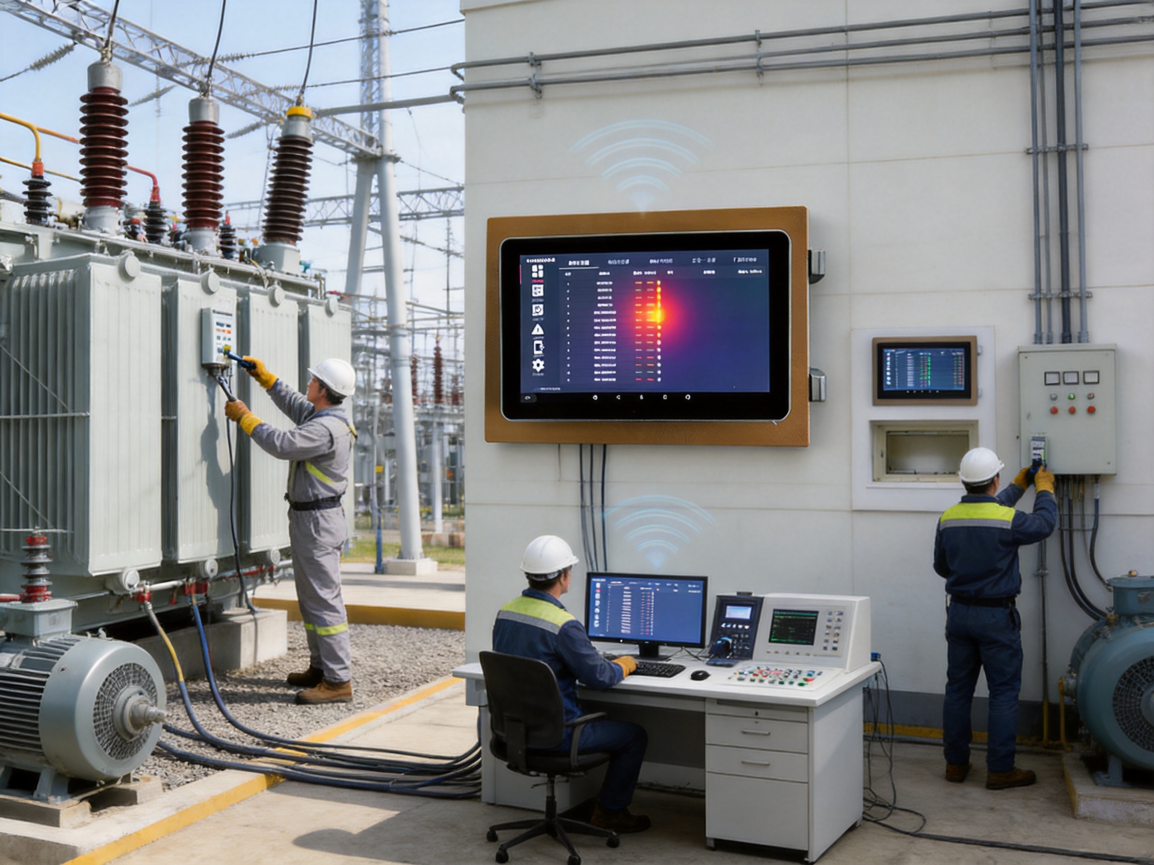
High-voltage electrical equipment operates under demanding conditions. Large currents, electrical stress, strong magnetic fields, restricted installation spaces, and changing environmental conditions can all contribute to abnormal heating. Contacts, busbar joints, transformers, high-voltage switches, outdoor disconnectors, motors, and industrial production equipment may gradually develop excessive temperature without producing an immediately visible warning. If the condition is not detected in time, the result can be equipment damage, unplanned shutdowns, insulation deterioration, fire, or a serious safety incident.
For this reason, online temperature monitoring has become an important part of modern power distribution and industrial asset management. A monitoring system must do more than measure temperature occasionally. It should collect data continuously, transfer information reliably from difficult measurement points, display operating conditions clearly, record alarm events, support communication with supervisory systems, and provide maintenance personnel with sufficient information to act before a minor thermal problem becomes a major failure.
The KL-MT89MP 10-inch wireless temperature measurement touchscreen unit is designed for this purpose. It functions as an industrial-grade wireless temperature monitoring host that receives information from wireless temperature sensors installed directly on high-voltage electrical equipment. With a color touchscreen, configurable alarm functions, event records, communication interfaces, relay output options, and support for at least 240 wireless sensors, the host provides a centralized solution for real-time thermal supervision.
Its value lies in the combination of wireless sensing, local visualization, network communication, alarm management, and industrial installation flexibility. Instead of requiring long sensor cables connected to every high-voltage contact, the system uses low-power wireless communication to transfer measurement data to the host. This arrangement helps overcome insulation, electromagnetic interference, space, and wiring challenges that commonly affect high-voltage temperature measurement projects.
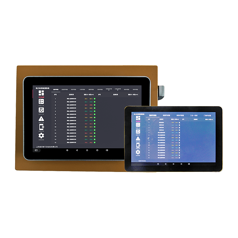
10-inch Wireless Temp Measurement Touchscreen Unit
Understanding the Thermal Risks in High-Voltage Installations
Temperature is one of the most useful indicators of electrical equipment condition. When a connection becomes loose, contact resistance increases. When a conductor is overloaded, heat generation rises. When a transformer or motor is subjected to abnormal operating conditions, its temperature may exceed the expected range. In each case, temperature data can reveal developing problems before visible damage occurs.
Traditional inspection methods often rely on periodic manual checks or handheld infrared instruments. These methods can be useful, but they have limitations. A manual inspection only represents the condition at a particular moment. It may not detect a fault that occurs between inspection rounds. Infrared inspection may also require access to the equipment, a suitable viewing angle, and an operating environment that permits safe observation. Some internal contacts and enclosed connection points are difficult or impossible to inspect externally.
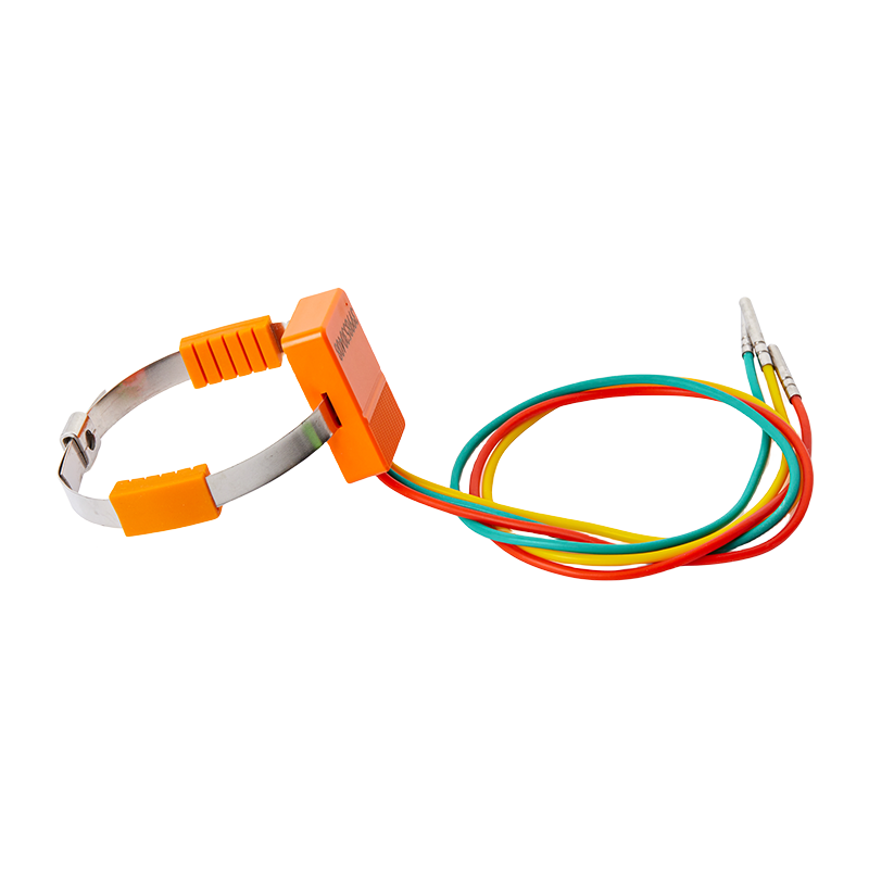
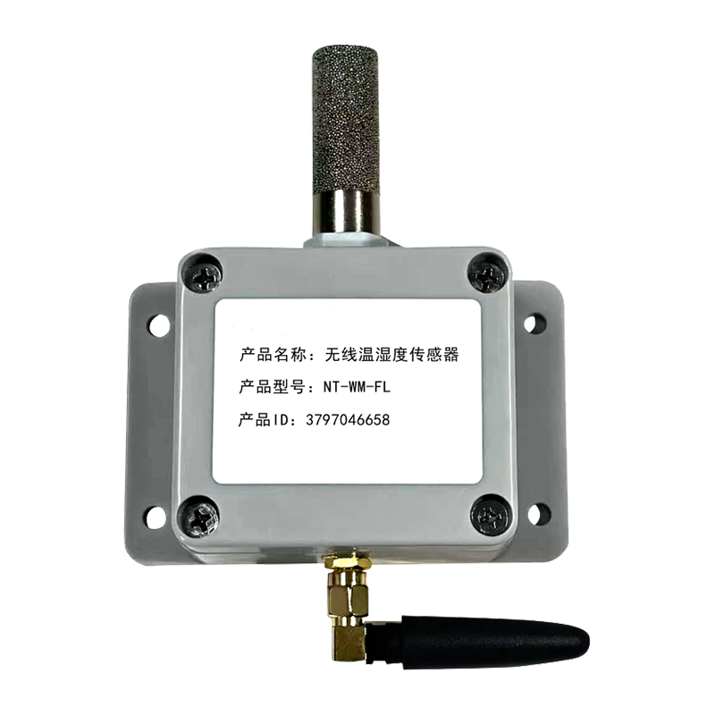
A permanently installed wireless sensor provides a different approach. The sensor remains at the measurement point and transmits temperature information to the monitoring host. This enables operators to observe thermal conditions continuously and to configure alarm thresholds for abnormal temperature. The monitoring host can also receive sensor operating voltage data, which helps maintenance personnel evaluate the condition of the wireless sensor itself.
High-voltage locations create special engineering requirements. A sensor must be compact enough for the available installation space, while the communication method must support reliable data transmission without creating an unsafe conductive path. The monitoring system must also tolerate industrial electromagnetic conditions and provide adequate insulation between the monitored equipment and the control or display system.
The wireless architecture addresses these requirements by separating the sensing point from the host through radio communication. This reduces the need for extensive signal wiring near high-voltage contacts and simplifies the connection between field sensors and the centralized display unit. The result is a monitoring arrangement that can be adapted to electrical cabinets, substations, industrial switchgear, busbar systems, transformers, motors, and other assets where thermal conditions are important.
Product Overview: A Centralized Wireless Temperature Host
The KL-MT89MP is a 10-inch touchscreen host for wireless temperature measurement. It receives data uploaded by wireless temperature sensors and presents the information to operators through a color display. The industrial-grade design is intended for applications that require permanent operation, centralized observation, local alarm handling, and integration with external control or monitoring platforms.
The host supports wireless frequencies of 2.4 GHz, 433 MHz, and 470–510 MHz, depending on the selected configuration. This range of available wireless options allows system designers to select a suitable communication band for the application, installation environment, and sensor configuration. The host can manage at least 240 wireless sensors, making it appropriate for installations that include many monitoring points distributed across electrical equipment.
In addition to wireless reception, the unit provides RS485, Ethernet, and fiber optic communication options. RS485 communication can reach up to 1,200 meters without repeaters under the stated conditions. The system supports Modbus communication and configurable baud rates of 1,200, 2,400, 4,800, and 9,600 bps. Up to 128 hosts can be connected within a network, allowing the monitoring architecture to be expanded across multiple equipment rooms, substations, production areas, or distributed industrial sites.
The host operates from AC220V and has an overall power consumption of no more than 5VA. Its specified operating temperature range is -10°C to +70°C, with operating humidity up to 90%RH under non-condensing and non-corrosive conditions. It can be installed using either wall-mounted or recessed installation methods, giving system integrators greater flexibility when planning control panels and equipment rooms.
Item |
Specification |
Product type |
10-inch wireless temperature measurement touchscreen host |
Wireless frequencies |
2.4 GHz, 433 MHz, or 470–510 MHz |
Wireless sensor capacity |
At least 240 wireless sensors |
Communication interfaces |
RS485, Ethernet, and fiber optic communication available |
RS485 communication distance |
Up to 1,200 meters without repeaters |
Network capacity |
Up to 128 hosts |
Communication protocol |
Modbus |
Baud rates |
1,200, 2,400, 4,800, and 9,600 bps |
Power supply |
AC220V |
Power consumption |
≤5VA |
Operating temperature |
-10°C to +70°C |
Operating humidity |
≤90%RH, non-condensing and non-corrosive |
Installation |
Wall-mounted or recessed |
How the Wireless Monitoring System Works
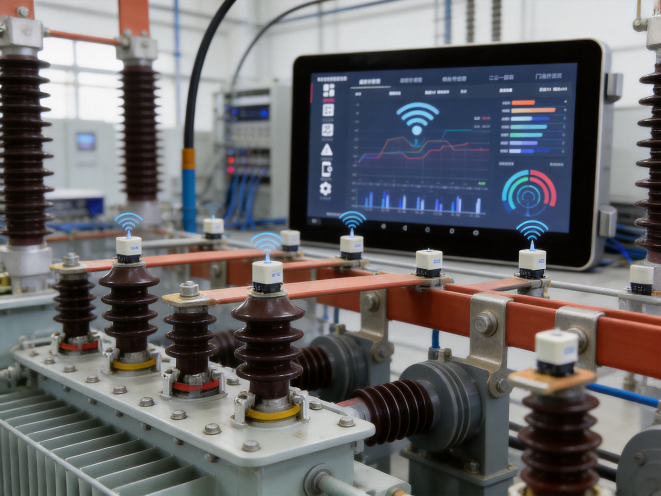
The system consists of wireless temperature sensors, the KL-MT89MP monitoring host, and optional external control or supervisory equipment. A sensor is installed at a selected temperature measurement point on high-voltage electrical equipment. It measures the local temperature and transmits the collected data through a low-power wireless network.
The monitoring host receives the temperature information and the sensor operating voltage uploaded by the wireless sensor. It then processes and displays the data in a clear color interface. Operators can view current temperatures, monitor the condition of multiple points, review alarm information, and adjust system parameters through the touchscreen interface.
When the temperature at a monitored point reaches an alarm threshold, the host can generate an audible buzzer warning. Where the optional relay dry contact function is provided, the host can also output a signal to an external alarm circuit, control system, or other equipment. The stated relay rating is AC220V/5A, passive normally open, subject to the selected configuration.
The host also records temperature data associated with alarm events. This record is valuable because it gives maintenance personnel more than an instantaneous warning. It establishes a history of when an alarm occurred and the temperature associated with the event. Such information can support fault investigation, maintenance planning, equipment replacement decisions, and post-incident analysis.
A real-time clock is included and serves as the time reference for event logging. Accurate event timing helps operators compare temperature changes with loading conditions, switching operations, process changes, ambient conditions, and maintenance activities.
Parameters can be adjusted through the host interface. The product information states that parameters remain stored even when power is off. Password management is used to protect settings. A user password supports routine access control, while a system password permits access to more advanced settings. This separation helps reduce the risk of accidental changes to critical operating parameters.
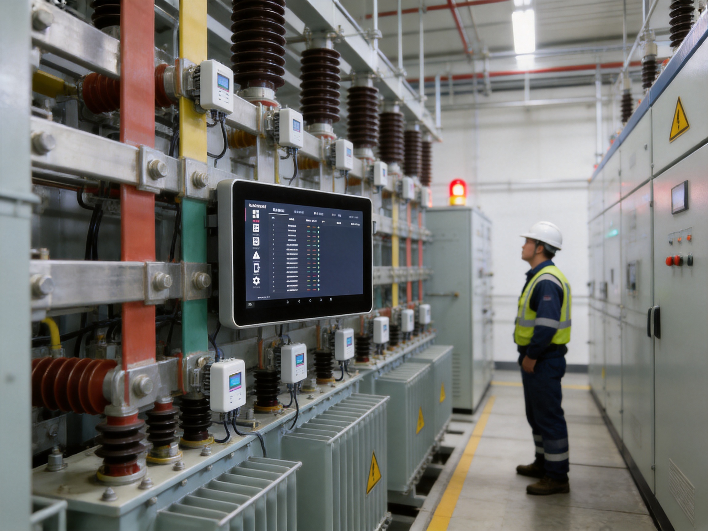
Advantages of Wireless Temperature Monitoring
Reduced Wiring at High-Voltage Measurement Points
The most important advantage of the system is the reduction of signal wiring near high-voltage contacts. Conventional wired temperature systems may require cables, terminals, insulation structures, and routing channels for every measurement point. In a crowded switchgear cabinet or compact electrical installation, adding this wiring can be difficult. It may also increase installation complexity and create additional considerations for insulation coordination and mechanical protection.
Wireless sensors communicate with the host without requiring a direct signal cable from each measurement point. This makes it easier to install sensors on busbar joints, switch contacts, transformer connections, motors, and other locations where cable routing is restricted. The approach can also reduce the amount of modification required for existing equipment, which is particularly useful when upgrading an operating plant.
Continuous Observation Instead of Periodic Inspection
Periodic inspection provides useful snapshots, but a wireless monitoring system supports ongoing observation. Temperature changes can be identified as they develop, and alarms can be generated when configured thresholds are reached. This supports a more proactive maintenance strategy.
Continuous data is especially valuable for equipment whose load varies during the day or across production cycles. A connection may remain within its normal range during low demand but become excessively hot during peak loading. A permanent sensor and host can capture these changes, whereas an inspection performed during a low-load period may not reveal the underlying issue.
Centralized Management of Many Sensors
With capacity for at least 240 wireless sensors, the host can consolidate information from a substantial number of monitoring points. This reduces the need for operators to inspect individual devices or separate local indicators. A centralized interface can organize data by equipment, location, or sensor address, depending on the configured application.
The ability to connect up to 128 hosts in a network further supports large installations. A plant may use one host in a distribution room, another in a production area, and additional hosts in remote electrical rooms. Network communication allows information to be exchanged with a broader monitoring architecture using appropriate system design and Modbus integration.
Flexible Industrial Communication
Different industrial facilities have different communication requirements. Some systems depend on RS485 because it is familiar, economical, and widely supported by industrial controllers. Others use Ethernet for integration with plant networks. Fiber optic communication may be preferred where electrical isolation, long-distance transmission, or immunity to certain electromagnetic conditions is important.
By making RS485, Ethernet, and fiber optic communication available, the product can adapt to a range of supervisory and control architectures. Modbus support also improves compatibility with industrial automation systems, data acquisition systems, and supervisory software that already use the protocol.
Local Alarm and Remote Integration
A monitoring system should provide a clear local warning even when a central supervisory platform is unavailable or not immediately observed. The host’s color display and buzzer alarm support local awareness. The optional relay output can transfer an alarm condition to external equipment, while communication interfaces allow data to be shared with other systems.
This combination of local and network-level notification improves response flexibility. An operator near the equipment can see and hear the alarm, while a control room system can receive the same information through the appropriate communication interface.
Protection Against Unintended Parameter Changes
Temperature alarm systems must be configurable, but configuration access should be controlled. The password management function helps prevent unauthorized or accidental changes to alarm limits, communication settings, and other parameters. A two-level password structure provides a distinction between routine user access and advanced system configuration.
Temperature Alarm Functions and Maintenance Value
The system includes configurable temperature alarm settings. The listed default parameters include an upper temperature limit of +90°C and a lower temperature limit of -20°C in one alarm parameter group. A second listed temperature alarm setting includes an upper limit of +60°C and a lower limit of -10°C. These values indicate that the system can support different alarm configurations according to the application or operating mode.
The listed alarm voltage value is 2,700 mV. Monitoring sensor operating voltage is important because a sensor with an abnormal power condition may not provide reliable data. By displaying both temperature and sensor voltage, the host gives maintenance personnel an additional diagnostic reference.
Alarm thresholds should always be selected according to the equipment manufacturer’s requirements, insulation class, operating load, ambient temperature, installation arrangement, and site safety procedures. The default values should not be treated as universal limits for every application. During commissioning, engineers should establish suitable warning and trip strategies in cooperation with the equipment owner and responsible electrical professionals.
Alarm records can support several maintenance activities. First, they can help identify recurring thermal events. If the same connection repeatedly reaches an alarm limit during peak operation, the issue may require mechanical inspection, torque verification, load balancing, contact replacement, or other corrective action. Second, records can help distinguish isolated incidents from gradual deterioration. Third, the timing and temperature history can support decisions about whether equipment can continue operating under controlled conditions or should be removed from service.
Thermal monitoring does not replace electrical testing, visual inspection, mechanical inspection, or protection systems. Instead, it adds a continuous condition indicator that strengthens the overall maintenance program. When combined with load data, switching records, vibration information, insulation testing, and maintenance history, temperature records can improve the accuracy of equipment condition assessments.
Touchscreen Operation and Operator Experience
A 10-inch touchscreen provides a practical balance between visibility and panel space. A small display may force operators to cycle through multiple screens or read compressed information. A larger display can present multiple sensor values, status indicators, alarm information, and system parameters in a more accessible format.
The color display improves visual differentiation between normal conditions, warnings, alarms, and system messages. This is particularly helpful in environments where operators must evaluate many monitoring points quickly. A controllable backlight allows the display to be adapted to different application environments and viewing conditions.
The touchscreen interface also reduces dependence on external computers for basic operations. Operators can view current data, check alarm status, configure parameters, and review relevant records directly at the host. This can shorten response time during field inspections and reduce the need to carry a separate service device for routine monitoring tasks.
At the same time, local operation does not prevent integration with a larger system. The available communication interfaces allow the host to serve as both a standalone display and a component within a plant-wide monitoring network. This dual role is useful for facilities that need immediate local access but also want centralized data collection.
Installation Flexibility for New and Existing Facilities
The host supports wall-mounted and recessed installation. Wall mounting can be suitable for equipment rooms, control areas, and retrofit projects where rapid installation is preferred. Recessed installation can provide a more integrated appearance within a control cabinet, panel, or operator station when the enclosure design allows it.
Before installation, engineers should evaluate the power supply, ambient temperature, humidity, ventilation, accessibility, and communication routing. The specified operating environment is -10°C to +70°C with humidity up to 90%RH, provided that conditions are non-condensing and non-corrosive. The host is specified for installation at altitudes up to 2,500 meters.
Electrical installation should be performed by qualified personnel. The AC220V supply should be protected according to site standards, and grounding and insulation practices should comply with the relevant application requirements. Communication wiring should be routed in a manner that reduces the possibility of damage, unintended interference, or mechanical stress.
The stated insulation resistance is at least 100MΩ under the specified test conditions of 10–30°C and relative humidity below 80%. This specification provides an important reference for equipment assessment, but complete system safety also depends on the installation enclosure, wiring, sensor construction, grounding, clearances, and the characteristics of the monitored high-voltage equipment.
Advanced Manufacturing and Engineering Strengths
The performance of an industrial monitoring host depends not only on its visible functions but also on the engineering process behind the product. A reliable system requires coordinated development of sensing, wireless communication, display hardware, embedded software, power circuits, communication interfaces, alarm functions, mechanical installation, and data management.
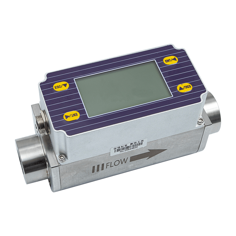
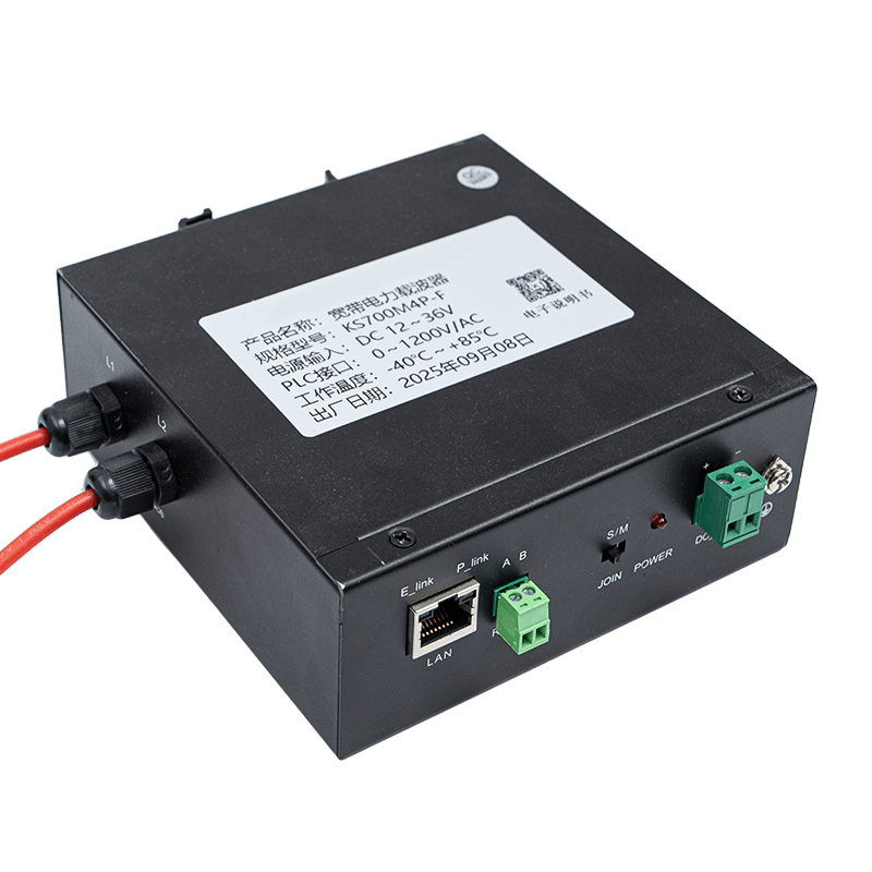
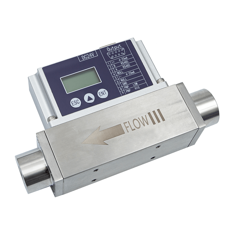
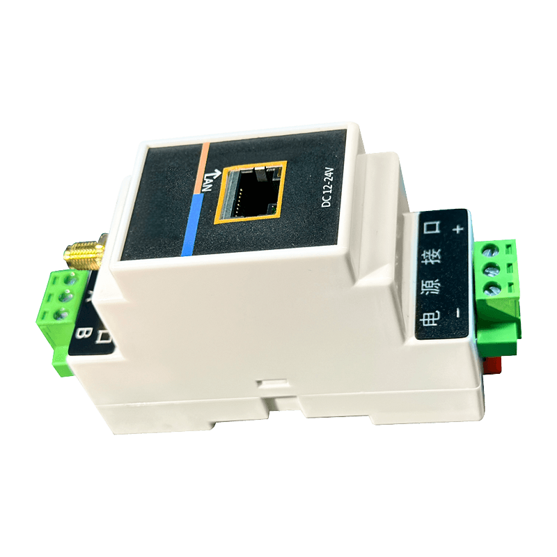
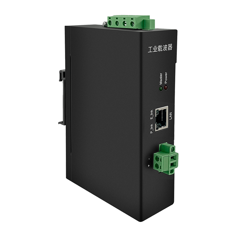
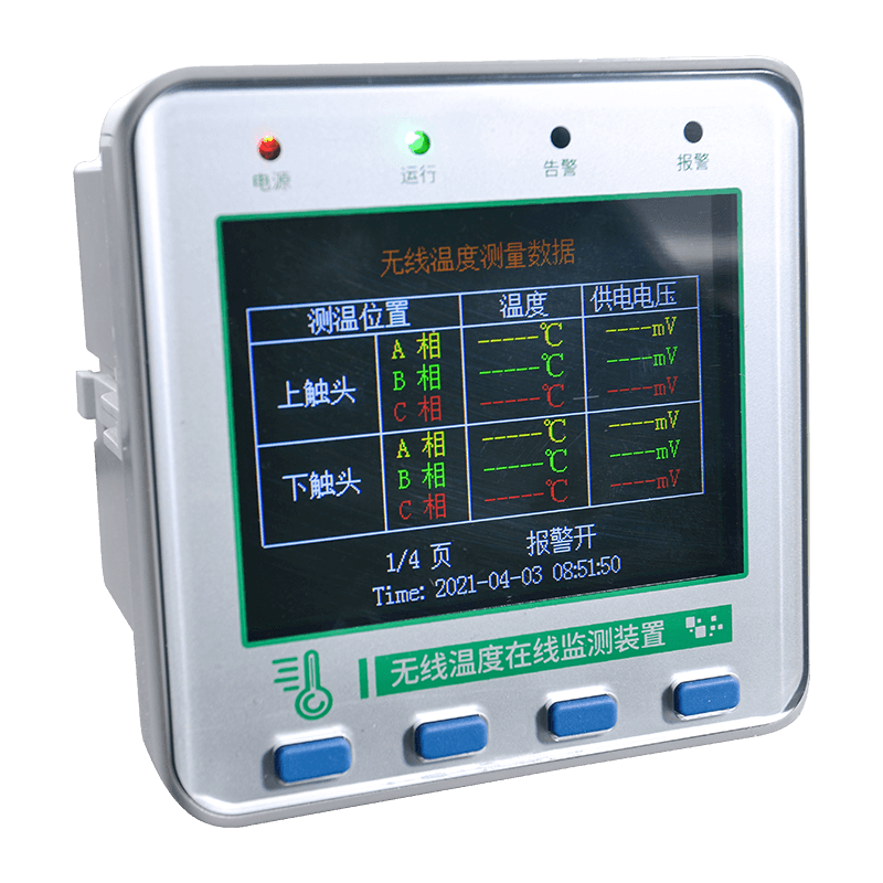
ASY Electronics is a high-tech enterprise focused on smart factory development, data sensing, and intelligent connectivity. Its product portfolio includes broadband power line carriers, wireless temperature monitoring systems, industrial transmitters, thermal gas mass flow meters, and automatic door controllers. This range indicates an engineering orientation that covers several layers of industrial automation, from field data acquisition to communication and equipment control.
The company’s stated capabilities include self-developed edge-layer hardware products and industrial data integration solutions. These capabilities are directly relevant to the wireless temperature monitoring host. Temperature sensors operate at the edge of the industrial system, while the host collects, organizes, displays, and communicates the resulting data. The ability to develop both hardware and integration functions helps support a more coherent system architecture.
Integrated Product Development
An integrated development approach can reduce the compatibility problems that sometimes occur when sensors, gateways, displays, and software are sourced from unrelated suppliers. For a wireless temperature monitoring system, the radio link, sensor data format, alarm logic, display functions, and communication protocol must work together consistently.
By developing a dedicated host for its wireless monitoring system, the company can align the host with the intended sensor network and application requirements. This supports more predictable commissioning, clearer parameter management, and easier technical communication between the equipment provider and the system integrator.
Manufacturing for Industrial Applications
Industrial products must be designed for repeatable production and stable field operation. The stated AC220V input, low power consumption, broad operating temperature range, insulation resistance specification, and flexible mounting methods reflect attention to practical installation requirements. These are not merely laboratory features; they are important considerations for equipment that may operate continuously in electrical rooms and industrial facilities.
A robust manufacturing process should include controlled assembly, inspection of electrical connections, functional verification of display and communication interfaces, testing of alarm outputs, and confirmation of storage and parameter retention. It should also verify that the final product corresponds to the configured wireless frequency and communication options required by the project.
Because the available product information does not specify individual factory test procedures or certifications, project purchasers should request the applicable inspection documentation, test records, compliance information, and quality-control details for the exact order configuration. This is a normal and recommended step in industrial procurement.
Data Sensing and Intelligent Connectivity
The company’s focus on data sensing and intelligent connectivity supports a broader smart-factory strategy. Equipment condition monitoring is more useful when data can move efficiently from a field device to a local host, then to a supervisory platform or maintenance database. The KL-MT89MP contributes to this chain by combining wireless sensor reception with industrial communication interfaces.
Its support for Modbus and multiple physical communication methods helps bridge field measurements with existing industrial systems. The use of standard communication concepts can reduce the need for proprietary integration and give system designers more options when connecting the host to control, monitoring, or energy-management platforms.
Application-Oriented Customization
Industrial facilities rarely have identical layouts. The number of monitoring points, communication distance, radio environment, alarm strategy, panel arrangement, and supervisory system may vary from one project to another. The host’s adjustable parameters, multiple communication options, wireless frequency choices, and wall-mounted or recessed installation support provide a foundation for application-specific configuration.
Customization should be understood as engineering adaptation rather than unrestricted modification. Project requirements should be reviewed in advance, including sensor count, radio frequency, communication topology, alarm relay requirements, data mapping, operating environment, and installation dimensions. Early coordination can help ensure that the selected product configuration matches the intended system.
Comparison with Conventional and Competing Approaches
Product comparisons should be based on application requirements rather than on a single specification. Nevertheless, the KL-MT89MP offers several practical advantages when compared with common alternatives.
Comparison area |
Conventional approach |
Wireless touchscreen host approach |
Connection to measurement points |
Multiple signal cables may be required |
Wireless sensors reduce signal wiring near high-voltage points |
Inspection method |
Periodic manual or infrared inspection |
Continuous online temperature monitoring |
Local visibility |
May require separate instruments or a control computer |
Integrated 10-inch color touchscreen |
Alarm response |
May depend on operator rounds or separate systems |
Local buzzer and optional relay dry-contact output |
Historical information |
May be limited if records are not automated |
Temperature alarm records and real-time clock support event review |
System expansion |
Expansion may require substantial additional wiring |
At least 240 wireless sensors per host and up to 128 hosts in a network |
System integration |
May rely on a proprietary interface |
RS485, Ethernet, fiber optic communication, and Modbus support |
Installation format |
May be limited to one panel arrangement |
Wall-mounted or recessed installation |
Compared with a basic local temperature indicator, the KL-MT89MP provides broader system management. It can receive data from many sensors, record alarms, provide password-protected configuration, and communicate with external systems. Compared with a fully wired measurement network, it can reduce wiring complexity at the high-voltage equipment level. Compared with an isolated wireless gateway that has no local interface, its touchscreen provides direct operator access and local alarm awareness.
Competitors may offer different sensor capacities, wireless frequencies, communication protocols, display sizes, or environmental specifications. Therefore, buyers should compare complete systems rather than host units alone. Sensor compatibility, radio performance, software functions, alarm behavior, data retention, installation requirements, and after-sales technical support should all be included in the evaluation.
Applications Across Industrial and Power Environments
High-Voltage Switchgear
Switchgear contains multiple conductive joints and contacts that may experience thermal stress. Wireless sensors can be installed at selected locations, while the host provides a centralized view of operating temperatures. Alarm records can help identify abnormal heating associated with contact resistance, loose connections, overload, or aging components.
Busbar Joints and Electrical Connections
Busbar joints are important monitoring points because a poor connection can generate localized heat. A wireless sensor system can support online observation without requiring a separate cable from each joint to a monitoring cabinet. The host can display the condition of multiple joints and provide alarm notification when configured limits are reached.
Transformers
Transformers may contain several connection points where temperature monitoring is useful. The system can be applied to selected electrical contacts and other temperature-sensitive points, subject to the sensor’s installation suitability and the transformer manufacturer’s requirements. Historical alarm information can support transformer maintenance planning.
High-Power Motors
Industrial motors operate under changing loads and may be exposed to demanding production conditions. Temperature monitoring can provide an additional indication of abnormal electrical or mechanical conditions. When integrated with other maintenance information, the host’s data can assist in identifying developing problems before they cause production interruption.
Outdoor Disconnectors
Outdoor disconnectors may face changing ambient temperature, moisture, and environmental exposure. The host is designed for a specified industrial operating range, while the suitability of each sensor and its mounting arrangement should be assessed for outdoor conditions. Proper enclosure, installation, and non-condensing environmental control remain essential.
Industrial Production Equipment
Many production systems contain high-current electrical connections, heaters, motors, drives, and switching devices. A wireless temperature monitoring network can add condition information to a broader smart-factory platform. The host’s communication capabilities make it suitable for projects that need to connect field temperature data with existing industrial data systems.
Recommended Implementation Process
Step One: Identify Critical Monitoring Points
The first step is to identify equipment where abnormal temperature could lead to safety risk, production loss, or expensive damage. Points may include busbar joints, cable connections, breaker contacts, transformer terminals, motor connections, and other high-current interfaces.
Step Two: Define Alarm Criteria
Alarm limits should be established from equipment ratings, historical operating data, ambient conditions, manufacturer recommendations, and site safety policies. It is often useful to define separate warning and critical alarm levels. The project team should determine whether a local buzzer, relay signal, supervisory alarm, or emergency shutdown action is required.
Step Three: Select Wireless Configuration
The wireless frequency should be selected according to the system design and available sensor configuration. The number of sensors, physical arrangement, electrical enclosure structure, distance, and radio environment should be considered. A site survey may be beneficial in complex installations with metal cabinets, thick walls, multiple floors, or strong sources of interference.
Step Four: Plan Communication Architecture
The project should determine whether the host will operate independently or connect to a larger system. RS485 may be appropriate for a local Modbus network, while Ethernet or fiber optic communication may be selected for broader integration. Addressing, baud rate, cable routing, network segmentation, and data mapping should be documented before commissioning.
Step Five: Install and Label Sensors
Each sensor should be installed securely at the designated measurement point and assigned a clear identification number. Labels should correspond to the equipment name, physical location, host address, and supervisory system tag. Accurate labeling is essential when many sensors are managed from a single display.
Step Six: Commission the Host
Commissioning should verify power supply, display operation, sensor registration, data reception, wireless communication, temperature values, sensor voltage values, alarm thresholds, clock settings, password access, communication parameters, and relay operation where applicable.
Step Seven: Test Alarm Scenarios
Alarm testing should confirm that the host displays the correct sensor location, activates the buzzer as intended, stores the event record, and transmits the appropriate signal to external systems. Testing should be performed under controlled procedures that do not endanger equipment or personnel.
Step Eight: Establish Maintenance Procedures
After commissioning, operators should periodically review sensor communication status, event records, alarm history, and unusual temperature trends. Maintenance personnel should inspect sensor mounting, host ventilation, electrical connections, and communication wiring according to site procedures.
Reliability, Security, and Lifecycle Benefits
Reliability in an industrial monitoring system includes measurement availability, communication stability, alarm visibility, parameter retention, and maintainability. The wireless monitoring architecture helps reduce physical signal wiring, while the host provides local display and alarm functions. The ability to record alarm temperatures supports traceability and makes it easier to investigate changes over time.
Security also includes operational control. Password management prevents every user from changing critical settings. Separate user and system passwords allow ordinary operation and advanced configuration to be managed at different levels. Facilities should still apply their own access-control procedures, password policies, and documentation practices.
Lifecycle value comes from early fault detection. A temperature monitoring system may help maintenance teams intervene before a connection failure causes an outage. Even when no alarm occurs, historical data can help demonstrate stable operation and support condition-based maintenance. This can reduce unnecessary replacement of healthy components while allowing attention to focus on assets showing abnormal behavior.
The low overall power consumption of no more than 5VA also supports efficient continuous operation. Although energy savings from the host itself may not be the primary reason for deployment, low consumption is beneficial in systems with many monitoring devices and supports the company’s stated goal of developing efficient, reliable, and green smart-factory solutions.
Role in Smart Factory and Smart Grid Development
Modern industrial facilities increasingly rely on connected data. A smart factory is not defined only by automated machinery; it also depends on the ability to collect accurate information from equipment, interpret operating conditions, and use that information to improve decisions. Temperature is a practical and actionable form of condition data.
The KL-MT89MP can serve as an edge-to-network component in this architecture. Wireless sensors collect information at the equipment level. The host organizes and displays the data locally. Standard communication interfaces allow the information to move toward supervisory systems, maintenance platforms, or plant-level dashboards.
In smart-grid applications, the same principle applies to substations, distribution equipment, and high-voltage electrical infrastructure. Continuous monitoring can improve visibility into assets that are difficult to inspect manually. When combined with power quality, load, vibration, insulation, and environmental data, temperature information can contribute to a more complete asset-management strategy.
ASY Electronics positions its broader business around smart factories, intelligent connectivity, equipment condition monitoring, refined energy management, and production process optimization. The wireless temperature host fits this direction by turning thermal conditions at difficult field locations into accessible operational data.
Selection Considerations for Buyers and System Integrators
Organizations evaluating a wireless temperature monitoring host should begin with the application rather than the product label. The number of required sensors, sensor placement, wireless frequency, environmental conditions, communication topology, alarm strategy, display requirements, and future expansion plans should be documented.
It is also important to confirm the exact product configuration. The listed wireless frequencies are available options, not necessarily simultaneous operating frequencies in every unit. Similarly, relay output is identified as an optional function. Buyers should verify which interfaces, frequency band, relay function, enclosure arrangement, and accessories are included in the quotation.
System integrators should review Modbus register mapping and confirm how temperature, sensor voltage, alarm status, event records, and device information will be represented. They should also confirm the number of sensors supported by the selected configuration and the intended network structure when multiple hosts are used.
Environmental evaluation is equally important. The host’s stated temperature and humidity range applies to the host installation conditions. Sensors installed on high-voltage equipment may face different thermal, mechanical, electrical, and weather conditions. Sensor suitability, mounting method, insulation requirements, and maintenance access should be assessed separately for each measurement point.
Q&A: Common Questions About the Wireless Temperature Host
What is the main function of the KL-MT89MP?
It is a 10-inch industrial touchscreen host that receives temperature and sensor operating voltage data from wireless temperature sensors. It displays the information, manages alarms, records temperature alarm events, and supports communication with external industrial systems.
How many wireless sensors can one host manage?
The stated capacity is at least 240 wireless sensors. The practical number used in a project should be confirmed according to the selected configuration, sensor type, wireless frequency, communication environment, and project requirements.
Which wireless frequencies are available?
The available wireless options are 2.4 GHz, 433 MHz, and 470–510 MHz. The correct selection depends on the sensor configuration, application environment, radio conditions, and project design.
Can the host communicate with a PLC or supervisory system?
Yes. The host supports RS485, Ethernet, and fiber optic communication options, and it uses the Modbus protocol. System integrators should confirm the selected physical interface and the required communication parameters before commissioning.
What baud rates are supported?
The listed baud rates are 1,200, 2,400, 4,800, and 9,600 bps. The selected rate should match the connected equipment and the communication design.
Does the host provide a local alarm?
Yes. When an alarm event occurs, the host can issue a buzzer alarm and display the relevant condition. An AC220V/5A passive normally open relay dry contact is available as an optional function for external alarm signaling.
Does the host record alarm history?
Yes. The system records the temperature at the measurement location where an alarm has occurred. A real-time clock provides the time reference for event logging.
Can users change alarm parameters?
Parameters are adjustable through the host interface. Password management is used, with user and system password levels. Alarm values should be configured by qualified personnel according to the monitored equipment and site procedures.
What power supply does the host require?
The operating voltage is AC220V, and the overall power consumption is no more than 5VA.
Where can the host be installed?
The host supports wall-mounted and recessed installation. The installation environment should remain within the specified temperature, humidity, altitude, insulation, and non-corrosive conditions.
Does wireless monitoring eliminate all maintenance work?
No. Wireless monitoring improves visibility and supports proactive maintenance, but it does not replace electrical testing, equipment inspection, sensor verification, or qualified maintenance procedures. It should be integrated into a complete asset-management program.
What makes this product suitable for smart-factory projects?
It combines field wireless sensing, local color touchscreen display, alarm management, event recording, Modbus communication, and multiple communication interfaces. These functions allow temperature information to be used locally and integrated into broader industrial data systems.
Conclusion
The KL-MT89MP 10-inch wireless temperature measurement touchscreen unit provides a practical approach to online thermal monitoring of high-voltage electrical equipment. By receiving data from wireless sensors installed directly at critical measurement points, it reduces the need for extensive signal wiring and makes continuous temperature observation more accessible in difficult industrial environments.
Its key strengths include support for at least 240 wireless sensors, multiple frequency options, a 10-inch color touchscreen, real-time clock functionality, adjustable parameters, password management, temperature alarm records, buzzer notification, optional relay output, Modbus communication, RS485, Ethernet, fiber optic interfaces, and flexible wall-mounted or recessed installation.
Compared with periodic inspection or basic local indicators, the host offers broader visibility, faster alarm awareness, and stronger integration potential. Compared with fully wired monitoring arrangements, its wireless architecture can simplify installation near high-voltage contacts. Its value is further strengthened by the manufacturer’s focus on data sensing, intelligent connectivity, edge-layer hardware, industrial data integration, condition monitoring, energy management, and smart-factory development.
For successful deployment, the system should be selected and commissioned as part of a complete engineering project. Sensor locations, wireless conditions, alarm limits, communication interfaces, installation environment, cybersecurity practices, and maintenance procedures should all be reviewed. When properly applied, the wireless temperature monitoring host can help industrial operators detect thermal abnormalities earlier, support condition-based maintenance, improve equipment reliability, and build a stronger foundation for connected power and manufacturing systems.
References
1. Product technical information for the KL-MT89MP wireless temperature measurement touchscreen host.
2. Industrial condition monitoring principles for electrical equipment and high-current connections.
3. Modbus communication concepts for industrial automation and supervisory data exchange.
4. General engineering practices for high-voltage equipment insulation, installation, and maintenance.
5. Smart-factory development principles involving data sensing, intelligent connectivity, equipment condition monitoring, and industrial data integration.