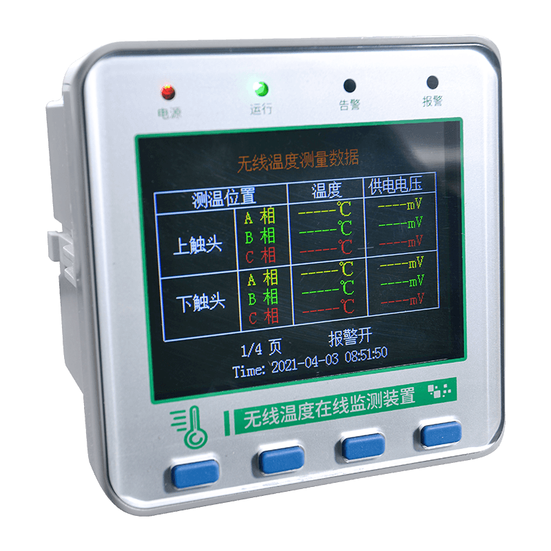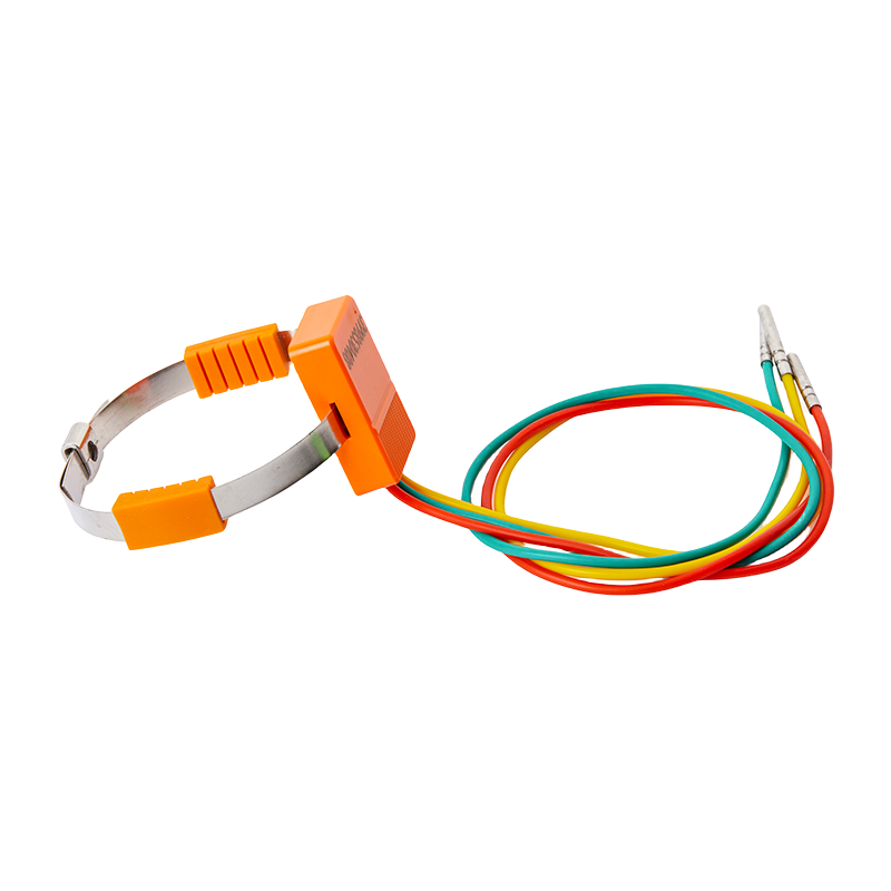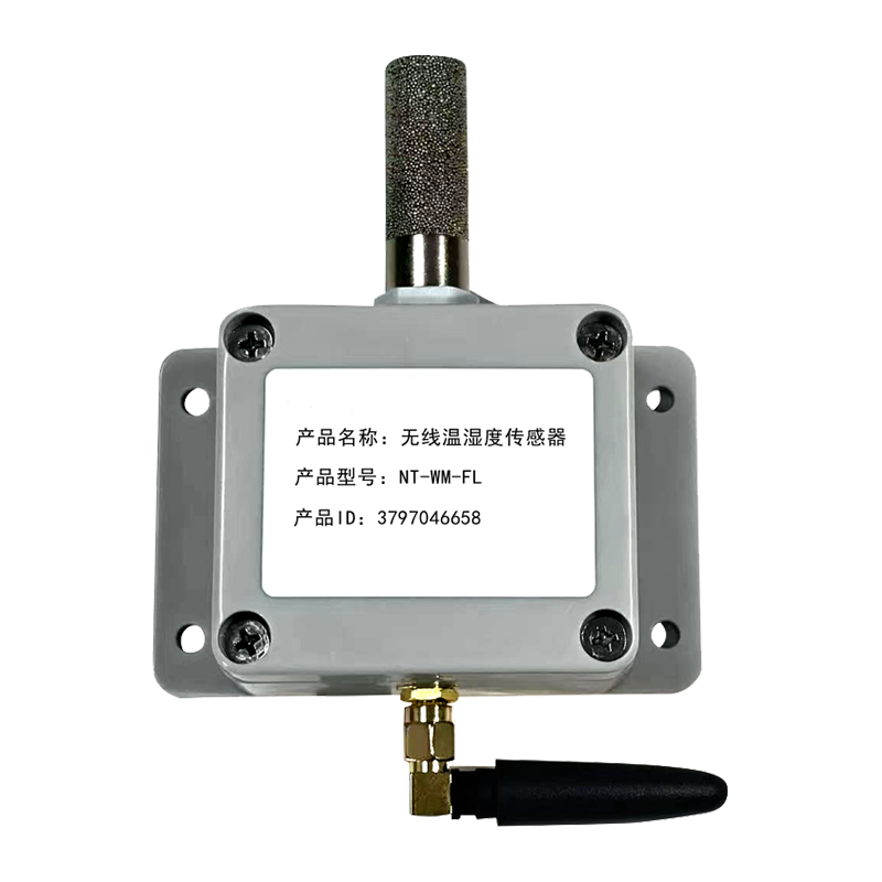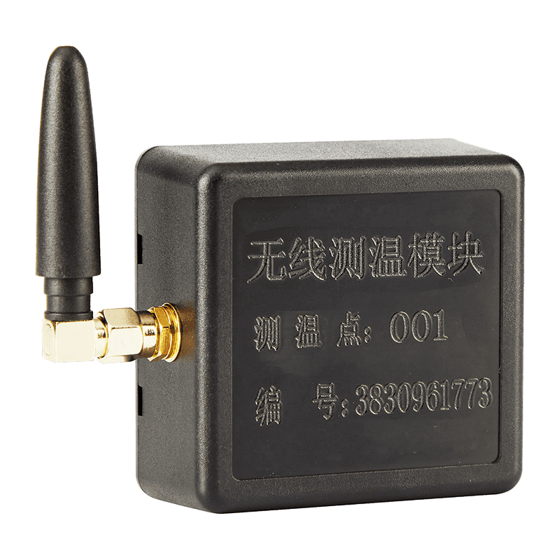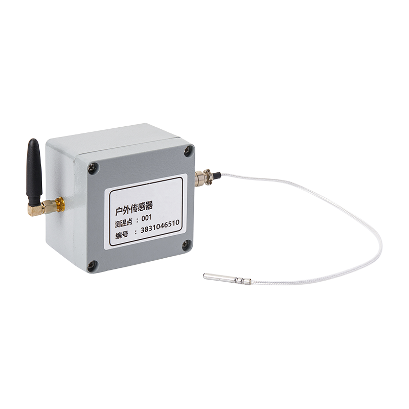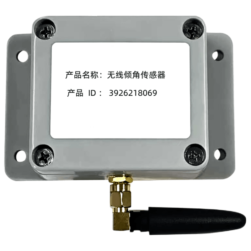


Industrial facilities increasingly depend on accurate, continuous, and accessible temperature information. Electrical cabinets, substations, switchgear, transformers, production machinery, pipelines, storage systems, and process equipment can all experience temperature changes before a visible failure occurs. When temperature data is collected continuously and transferred to a control system, operators can identify abnormal heating, arrange preventive maintenance, and reduce the risk of costly downtime.
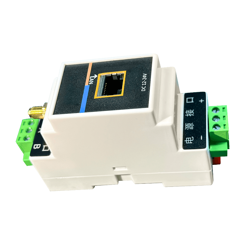
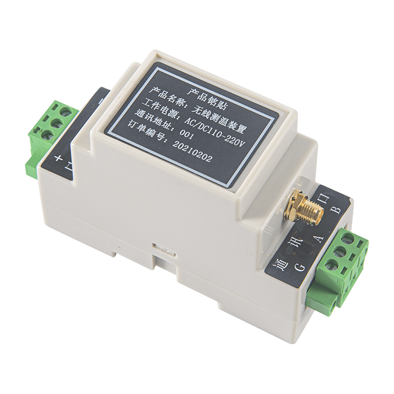
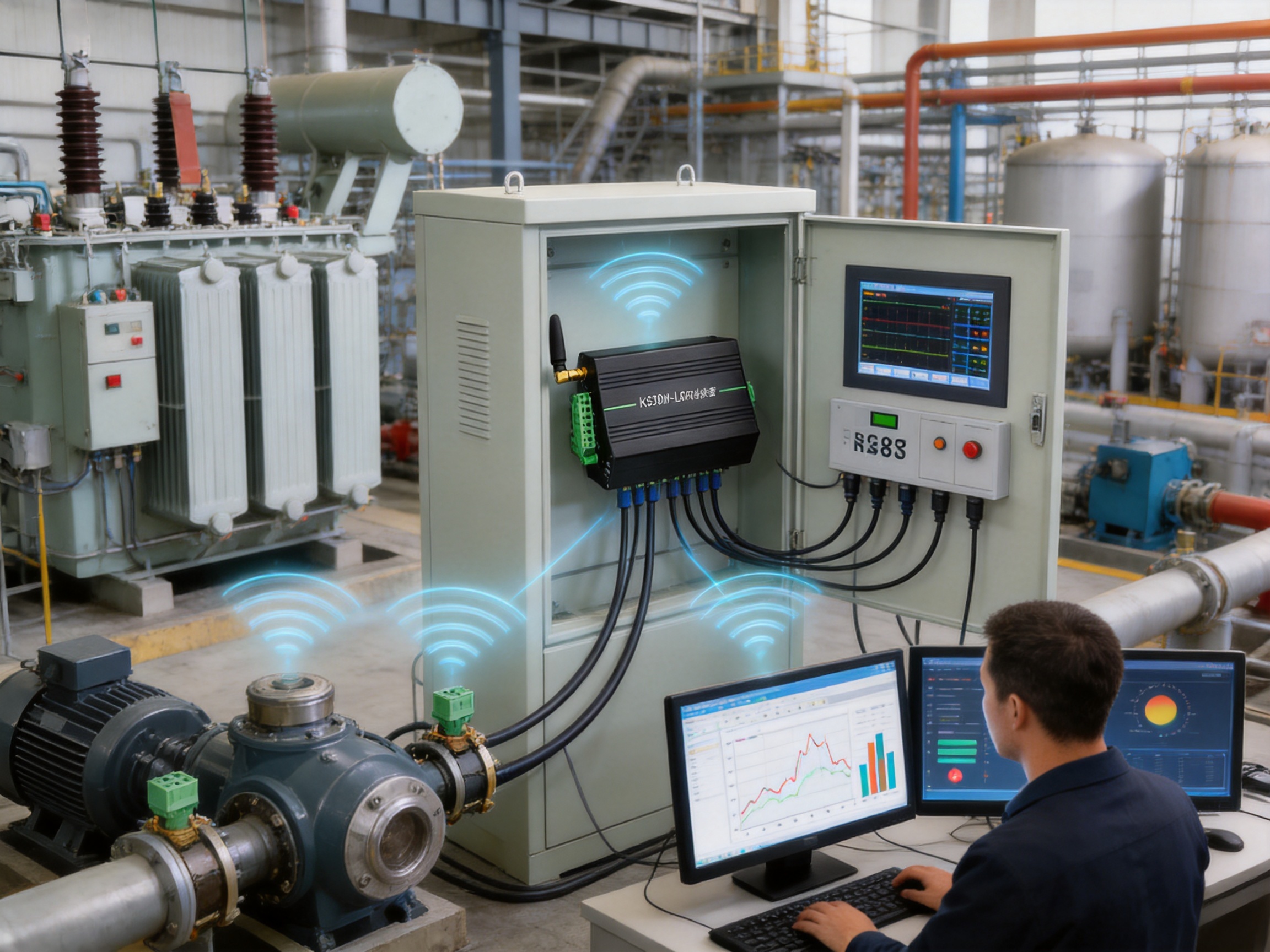
The KS30M-LORA wireless temperature measurement host is designed to serve as the receiving and communication center of an industrial wireless temperature monitoring system. It receives data from wireless temperature sensors, organizes the incoming information, and makes the data available to supervisory equipment through RS485 communication. With support for the standard MODBUS RTU protocol, a maximum capacity of 240 sensors, DIN rail installation, a metal enclosure, and a wide AC/DC power supply range, the unit is suitable for demanding industrial environments.
Rather than functioning as a simple wireless receiver, the host provides a practical connection between field-level sensing devices and industrial automation, energy management, or equipment monitoring platforms. It is intended for applications where reliable data collection, straightforward integration, flexible installation, and long-term serviceability are more important than consumer-oriented features.
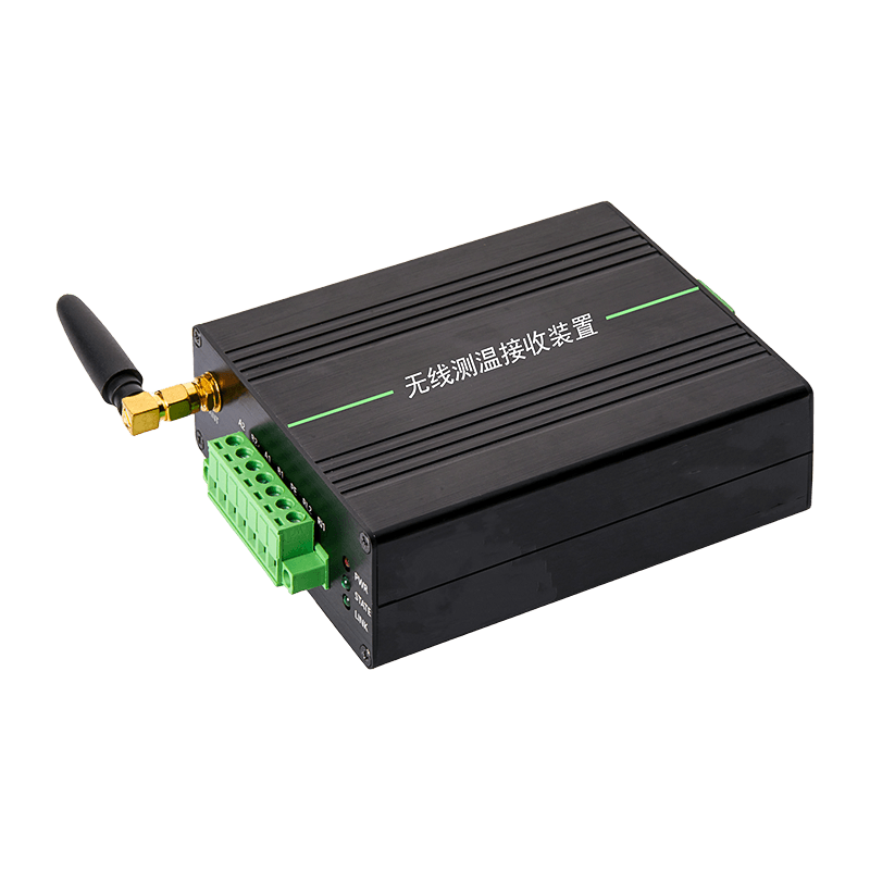
Metal Enclosure Version Guide Rail Temperature Measurement Unit
Product Role in an Industrial Temperature Monitoring System
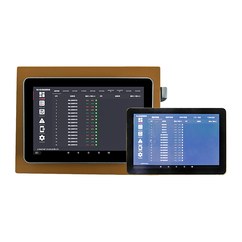
A wireless temperature monitoring system normally contains three principal layers. The first layer is the sensing layer, consisting of temperature sensors installed on the equipment being monitored. The second layer is the wireless receiving layer, which collects radio signals from those sensors. The third layer is the communication and management layer, which passes the collected data to a programmable logic controller, human-machine interface, supervisory control and data acquisition system, industrial computer, or other host platform.
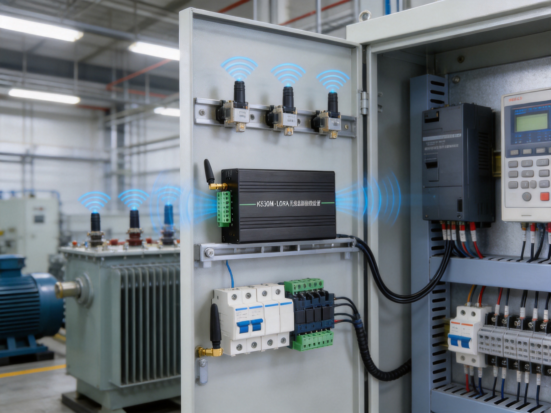
The KS30M-LORA occupies the receiving and communication position between the wireless sensors and the industrial control network. Sensors are installed on or near the target equipment and transmit their measurements through radio waves. The receiving host captures the wireless data and provides a wired RS485 interface for communication with external systems.
This structure reduces the amount of signal cabling required in the monitored area. In many industrial installations, adding cables to rotating equipment, high-voltage equipment, enclosed cabinets, elevated structures, or difficult-to-access areas is expensive and disruptive. A wireless sensor network can simplify installation while preserving a clear path to the central monitoring system.
The host is particularly appropriate for facilities that need to monitor many points from a centralized location. With a maximum connection capacity of 240 sensors, one receiving unit can support a substantial monitoring network. The actual number of sensors used in a project depends on the radio environment, installation conditions, communication design, and the requirements of the application, but the stated capacity provides a strong foundation for medium-scale and large-scale deployments.
Key Product Advantages
High-Capacity Sensor Management
One of the most important advantages of the product is its ability to receive data from up to 240 sensors. Generic wireless gateways designed for small building automation systems may support only a limited number of endpoints or may require several gateways as the application grows. A high-capacity receiving host can reduce the number of gateway devices, simplify network planning, and create a more centralized architecture.
Fewer receiving units can also reduce the number of power supplies, communication addresses, cabinets, and maintenance points in the system. For an industrial operator, this may result in a cleaner control-panel layout and easier troubleshooting. The capacity is especially valuable in substations, distribution rooms, manufacturing plants, warehouses, and process facilities where a large number of temperature points must be monitored simultaneously.
The system also supports sensor ID settings. Assigning an identifiable address to each sensor allows the monitoring platform to distinguish individual measurement points. This is essential when many sensors are installed across different cabinets, motors, busbars, production lines, or zones. Clear identification helps operators associate each temperature value with the correct physical location and improves the usefulness of alarm and maintenance records.
Wireless Data Collection with Industrial Integration
The product combines wireless field sensing with RS485 wired communication. This combination offers a practical balance between installation flexibility and industrial reliability. Sensors can be placed where cabling is inconvenient, while the receiving host can be connected to established control equipment through a familiar industrial interface.
RS485 is widely used in industrial automation because it supports robust differential signaling and can operate over practical distances when correctly installed. Maintenance personnel and system integrators are generally familiar with RS485 wiring, termination, addressing, and fault diagnosis. The product therefore does not require a completely new communication infrastructure for facilities that already use serial industrial networks.
The unit provides two-channel 485 communication output, which offers additional flexibility for connecting external equipment or separating communication paths according to project requirements. The available communication method is RS485, and the default communication settings are 9600 baud, 8 data bits, 1 stop bit, and no parity verification. The standard MODBUS RTU protocol further improves compatibility with industrial controllers and monitoring software.
Standard MODBUS RTU Protocol
Protocol compatibility is a significant factor in the selection of an industrial monitoring device. A gateway that requires a proprietary software environment can increase engineering work, training requirements, and long-term dependence on a single platform. By using standard MODBUS RTU communication, the host can be incorporated into many existing automation architectures.
MODBUS RTU is commonly supported by programmable logic controllers, data acquisition modules, energy management systems, industrial computers, and supervisory software. The integrator can read measurement values and related sensor information through an established register-based communication method. This makes the host suitable for retrofit projects as well as new installations.
The standard protocol can also simplify expansion. When a customer adds additional sensors, cabinets, or monitoring zones, the communication design can continue to use the same general industrial data structure. This helps reduce the need for extensive software redevelopment and allows engineering teams to focus on sensor placement, alarm logic, and application-level functions.
Metal Enclosure and DIN Rail Installation
The KS30M-LORA uses a metal enclosure and supports guide rail installation. A metal enclosure is well suited to industrial control cabinets because it provides a more substantial mechanical structure than many lightweight plastic gateway housings. It can help protect internal electronics from routine handling, vibration, and installation-related stress when correctly mounted in a suitable enclosure.
DIN rail installation is another practical advantage. The guide rail format is familiar in electrical control panels, distribution boxes, instrumentation cabinets, and industrial automation systems. It allows the host to be installed alongside circuit breakers, terminal blocks, relays, PLC modules, communication devices, and power supplies without requiring a custom mounting plate.
The product also supports screw installation. This gives system designers more freedom when the receiving host is placed in a nonstandard cabinet, wall-mounted box, equipment enclosure, or other location where a DIN rail is unavailable. Offering both guide rail and screw installation reflects a practical design approach focused on field conditions rather than a single fixed installation scenario.
Wide Power Supply Compatibility
The working power supply is AC/DC 100–240 V. This wide input range supports common industrial and commercial power arrangements and reduces the need for a specialized external power conversion stage in many installations. A broad input range can be useful for facilities with different regional electrical standards or for projects where the same product is deployed across multiple sites.
Using a product that accepts both alternating and direct current can also give integrators greater flexibility in control cabinets. Depending on the project design, the host may be connected to an available AC supply or an existing DC control power system. The appropriate wiring and protection method should always be selected according to the installation manual, local regulations, and the characteristics of the power source.
Useful Electrical and Sensor Data
The product is designed to handle temperature parameters and voltage parameters transmitted by the sensors. Temperature data is represented as 16-bit data with the most significant digit first. The stated temperature resolution is 0.1°C, with an error of ±1°C. This provides a practical level of detail for equipment condition monitoring and thermal trend analysis.
Voltage data is also represented as 16-bit data with the most significant bit first. For an active sensor, this value indicates battery voltage. For a passive sensor, the value represents the voltage after rectification and regulation. Having access to voltage information can help maintenance personnel evaluate sensor power status, identify declining battery conditions, or confirm the operating state of passive sensing equipment.
In an industrial monitoring application, temperature values should not be considered in isolation. A gradual increase in temperature may indicate changing load, ventilation problems, loose connections, bearing deterioration, insulation degradation, or other developing conditions. Sensor voltage information can help distinguish a true equipment trend from a possible field-device power problem.
Technical Specifications
| Item | Specification | Application Significance |
|---|---|---|
| Product model | KS30M-LORA | Wireless temperature measurement receiving host |
| Enclosure | Metal enclosure | Suitable for industrial control cabinet applications |
| Installation | DIN rail installation and screw installation | Supports standard panels and customized enclosures |
| Working power supply | AC/DC 100–240 V | Flexible connection to common industrial power systems |
| Maximum number of sensors | 240 | Supports centralized monitoring of many measurement points |
| Wireless frequency band | Sub-GHz, default 433 MHz | Designed for wireless field data collection |
| Wired communication | RS485 | Compatible with common industrial communication architectures |
| RS485 output | Two-channel 485 communication output | Provides flexible communication connection options |
| Communication protocol | Standard MODBUS RTU | Facilitates integration with PLCs, SCADA systems, and industrial software |
| Default baud rate | 9600 Bps | Suitable for standard serial communication setups |
| Data format | 8 data bits, 1 stop bit, no parity | Simple default serial configuration |
| Temperature data | 16-bit, most significant digit first | Provides structured digital measurement data |
| Temperature resolution | 0.1°C | Supports detailed temperature trending |
| Temperature accuracy | Error of ±1°C | Suitable for general industrial condition monitoring |
| Sensor ID | Configurable | Allows individual sensors to be identified |
| Relay dry contact | AC220 V/5 A, one set of passive normally open/normally closed contacts | Can support external alarm or control circuit requirements |
| Ambient temperature | –25°C to +70°C | Supports a broad range of industrial environments |
| Ambient humidity | ≤95% | Suitable for humid environments when installed correctly |
| Atmospheric pressure | 80–110 kPa | Supports ordinary industrial altitude conditions |
| Altitude | ≤2,500 meters | Applicable to many standard inland and industrial sites |
Environmental Performance for Industrial Deployment
The host is specified for an ambient temperature range of –25°C to +70°C. This range covers many indoor industrial spaces, electrical rooms, equipment cabinets, utility areas, warehouses, and sheltered outdoor enclosures. The product can therefore be considered for facilities that experience seasonal temperature changes or elevated cabinet temperatures.
The specified ambient humidity is no more than 95 percent. High humidity is common in some manufacturing plants, utility rooms, chemical facilities, transportation sites, and coastal regions. Although the host has a broad humidity specification, correct installation remains important. The unit should be protected from direct water spray, condensation, corrosive substances, and environments outside the stated operating conditions.
The atmospheric pressure specification is 80–110 kPa, and the rated altitude is up to 2,500 meters. These parameters define the environmental conditions under which the equipment is intended to operate. For high-altitude projects or installations with unusual atmospheric conditions, the system designer should confirm suitability before deployment.
Environmental specifications are not only product data-sheet values; they are also important inputs for project engineering. The cabinet location, ventilation, heat dissipation, moisture protection, cable routing, grounding, and surge protection should all be considered when installing the host. Proper system design allows the hardware to deliver its intended service life and communication performance.
Comparison with Conventional Monitoring Approaches
Compared with Fully Wired Temperature Monitoring
A fully wired temperature monitoring system can provide dependable communication, but it often requires extensive cabling from every measurement point to a central cabinet. In large facilities, the cable route may pass through cable trays, walls, high-voltage areas, moving mechanisms, or difficult-to-access structures. Installation can require shutdowns, mechanical modification, additional terminal blocks, and considerable labor.
A wireless sensor network reduces the amount of field wiring needed. The KS30M-LORA host preserves a wired RS485 connection at the control-panel level while allowing field sensors to communicate wirelessly. This hybrid architecture can be more convenient than either a completely wired field network or a consumer-style wireless system with no industrial interface.
Wireless communication is not automatically superior in every application. Radio interference, metal structures, distance, obstacles, and site layout must be evaluated. However, when the radio design is properly engineered, the combination of wireless sensors and a centralized industrial receiving host can provide an efficient alternative to extensive point-to-point cabling.
Compared with Small-Capacity Wireless Gateways
Many general-purpose wireless gateways are intended for homes, offices, or small commercial facilities. They may provide limited endpoint capacity, proprietary communication methods, plastic housings, or network interfaces designed primarily for internet connectivity. Such products may not be optimized for control cabinets, high sensor counts, or direct integration with serial industrial systems.
The KS30M-LORA is differentiated by its industrial positioning. Its 240-sensor capacity, metal DIN rail enclosure, RS485 connectivity, MODBUS RTU protocol, configurable sensor IDs, and relay dry contact provide functions that are directly relevant to equipment monitoring and automation. These features can reduce the need for additional protocol converters or custom interface hardware.
For a project manager, the advantage is not merely the number of sensors. It is the combination of capacity, installation format, communication compatibility, and industrial data handling in a single host. This can simplify procurement and reduce the number of separate devices that must be coordinated during system commissioning.
Compared with Proprietary Monitoring Platforms
Some monitoring solutions require a dedicated cloud platform, specialized software, or a proprietary controller. These systems may be convenient for certain users but can create challenges in factories that already have established PLC, SCADA, or energy management infrastructure. Data ownership, system expansion, long-term software support, and integration cost should all be considered.
The use of MODBUS RTU gives the KS30M-LORA a more open integration profile. The receiving host can be treated as an industrial field device within a larger automation design. Customers can use their existing monitoring software and control logic, subject to correct register mapping and communication configuration.
This open approach may be particularly valuable for industrial customers that require local data processing, independent control networks, or long equipment lifecycles. It also allows system integrators to select the upper-level platform according to the project rather than being forced into a single software ecosystem.
Relay Dry Contact Function
The host includes one set of passive normally open and normally closed relay contacts with a stated rating of AC220 V/5 A. A dry contact can be used as an interface to an external alarm circuit, warning indicator, control relay, or building and equipment management system, depending on the application design.
This function can be useful when the customer requires a simple hardware-level response to a temperature event. For example, an external circuit may use the contact to activate an audible alarm, send a signal to a control panel, or initiate a separate response process. The relay output can provide a direct electrical interface without requiring every alarm decision to be handled by a remote software platform.
Relay contacts must be used within their electrical rating and in accordance with the product documentation. The contact is not a substitute for a complete safety control system, emergency shutdown circuit, or certified protection relay. For high-energy equipment, the relay should normally be connected through an appropriately designed intermediate control circuit and protected according to local electrical standards.
Industrial Applications
Power Distribution and Substations
Temperature monitoring is important in switchgear, distribution cabinets, busbar connections, cable joints, transformers, and other power infrastructure. Loose connections and overloaded components can generate abnormal heat before an outage occurs. Wireless sensors can be installed at selected points, while the receiving host collects the information for a control-room or substation monitoring system.
The metal enclosure and DIN rail format are well suited to electrical cabinets. RS485 and MODBUS RTU allow the temperature system to communicate with existing automation equipment. The high sensor capacity also supports monitoring across multiple cabinets or equipment sections from a centralized host.
Petroleum and Chemical Facilities
Petroleum and chemical plants often contain equipment distributed across complex process areas. Temperature can be an important indicator of equipment condition, process stability, and abnormal operation. Wireless monitoring can reduce cable installation requirements around tanks, pumps, motors, pipe racks, and auxiliary equipment.
Site-specific safety requirements must be reviewed before installation. The product information provided does not state an explosion-proof certification, hazardous-area approval, or intrinsically safe rating. Therefore, the host and associated sensors should be used only in locations where their certifications and environmental ratings meet the project requirements. In classified hazardous areas, an approved protection concept is essential.
Railway Systems
Railway facilities include substations, signaling equipment, communication cabinets, station systems, and maintenance infrastructure. Temperature monitoring can support preventive maintenance and help identify thermal problems in electrical and control equipment. The receiving host can be installed in a control cabinet and connected to a local supervisory network through RS485.
Railway projects often require careful consideration of electromagnetic compatibility, vibration, power quality, environmental exposure, and sector-specific standards. The product should be evaluated against the applicable railway procurement and installation requirements before use in critical railway applications.
Mining and Metallurgy
Mining and metallurgical operations frequently involve high-power equipment, motors, conveyors, crushers, furnaces, electrical rooms, and harsh operating environments. Thermal monitoring can help maintenance teams identify overheating bearings, cabinets, connections, and drive equipment.
The host’s wide ambient temperature range, metal housing, and industrial communication interface make it a practical candidate for controlled indoor locations and suitable equipment enclosures. In dusty, wet, corrosive, or explosive locations, additional enclosure protection and certification assessment may be required.
Cement and Building Materials
Cement plants and building-material facilities contain motors, fans, conveyors, crushers, kilns, control cabinets, and material-handling systems. Many of these assets operate continuously and are distributed across a large area. Wireless temperature monitoring can help reduce the wiring burden and provide data for preventive maintenance.
For facilities with high dust levels, the receiving host should normally be placed inside a properly rated control cabinet or protected electrical room. Sensor selection and installation should be adapted to the temperature, vibration, dust, and mechanical conditions at each measurement point.
Manufacturing Plants and Smart Factories
Modern manufacturing facilities increasingly combine condition monitoring, energy management, production data, and equipment control. Temperature is one of the most accessible indicators for identifying abnormal equipment behavior. The KS30M-LORA can serve as a field communication component within a broader smart-factory architecture.
Data from the host may be combined with operating current, vibration, pressure, flow, production status, or maintenance records. This allows the customer to develop more meaningful equipment health models rather than relying on isolated temperature readings. The host is therefore suitable as part of a wider industrial data-sensing and intelligent-connectivity strategy.
Manufacturing and Engineering Strengths
The product is supplied by ASY Electronics (JiaXing) Co., Ltd., a high-tech enterprise focused on smart-factory technologies, industrial sensing, and intelligent connectivity. Its product portfolio includes broadband power line carriers, wireless temperature monitoring systems, industrial transmitters, flow meters, and automatic door controllers. This range indicates experience across sensing, communication, measurement, and industrial control applications.
A significant strength is the combination of edge-layer hardware development and industrial data integration. A wireless temperature host is not useful merely because it can receive radio signals. It must also present the data in a form that can be used by industrial systems. Experience with transmitters, flow measurement, power line communication, and control products can support a broader understanding of field wiring, measurement signals, protocol conversion, and plant-level integration.
The company’s stated mission is to support efficient, reliable, and green smart factories. This orientation is relevant to temperature monitoring because condition-based maintenance can help customers reduce unnecessary component replacement, avoid unplanned shutdowns, and improve the use of maintenance resources. Reliable data collection is an important foundation for achieving these goals.
Product-Oriented Engineering
Industrial equipment must be designed around actual installation conditions. The KS30M-LORA reflects several field-oriented decisions: a metal enclosure, guide rail mounting, screw mounting, a broad input power range, industrial RS485 communication, configurable sensor IDs, and a high sensor capacity. These features address common engineering requirements rather than focusing only on appearance or consumer convenience.
Product engineering also involves the definition of data structures and communication parameters. The use of 16-bit temperature and voltage data, most significant digit first formatting, sensor ID registers, and MODBUS RTU communication provides a structured basis for system integration. Clear data organization helps software developers and automation engineers build reliable polling and alarm functions.
Manufacturing for Consistent Industrial Hardware
Industrial customers need repeatable products. Consistency in enclosure assembly, connector installation, circuit-board production, firmware loading, communication testing, and final inspection is essential when multiple units are deployed across a plant or across several sites. A professional manufacturing process should control these stages through documented work instructions, traceability, inspection procedures, and functional testing.
For a product such as the KS30M-LORA, manufacturing quality is closely connected to communication stability. The wireless receiving circuit, power supply section, RS485 interface, relay output, and internal connections must work together reliably. Production testing should therefore verify not only whether the device powers on, but also whether its communication functions, configuration functions, and interface behavior meet the intended design.
The metal housing and industrial mounting structure also require attention to mechanical quality. Correct enclosure assembly, secure terminal connections, consistent rail clips, and suitable internal spacing help reduce installation problems. These details matter because the receiving host may remain in service for years, often in cabinets that are opened only during maintenance or expansion.
System Integration Capability
Manufacturing strength is especially valuable when it is supported by application engineering. Customers may need help with sensor matching, wireless parameter configuration, MODBUS communication, sensor addressing, relay usage, and installation planning. A supplier that understands both the hardware and the industrial application can help reduce commissioning time.
Because the company develops products for smart factories and industrial communication, it can support projects that involve more than a single monitoring device. A customer may begin with wireless temperature monitoring and later add transmitters, flow meters, power line communication equipment, or other data-sensing products. A broader product portfolio can make it easier to build a coordinated industrial data architecture.
Recommended System Design Process
Step One: Define the Monitoring Objectives
Before selecting sensor locations, the customer should define what the monitoring system must accomplish. The objective may be early warning of electrical overheating, trend analysis of rotating machinery, protection of stored materials, monitoring of process temperature, or verification of operating conditions.
The objective determines the required temperature range, measurement frequency, alarm limits, sensor type, communication layout, and data retention approach. It also determines whether the system is intended for advisory maintenance, process supervision, or a more critical protection function.
Step Two: Identify Measurement Points
Measurement points should be selected according to failure modes and operating conditions. Common locations include cable joints, terminal connections, motor housings, bearings, switchgear contacts, transformer surfaces, pipe sections, storage areas, and process equipment. Sensors should be installed where temperature changes are meaningful and where they can be secured against vibration or accidental impact.
Sensor placement should not be based only on convenience. A sensor installed too far from the heat source may respond slowly or fail to represent the actual condition. Conversely, a sensor installed in a location exposed to excessive mechanical or environmental stress may require additional protection.
Step Three: Plan the Wireless Network
The default wireless frequency band is Sub-GHz, with 433 MHz specified as the default frequency. The radio environment should be assessed before final installation. Metal cabinets, concrete walls, large machines, high-voltage equipment, and other obstructions may affect signal behavior. The distance between sensors and host, antenna orientation, cabinet position, and surrounding radio equipment should all be considered.
A site survey or pilot installation is recommended for large or complex facilities. The survey can identify weak signal zones, interference sources, and locations where the host or sensors should be repositioned. Wireless planning is particularly important when sensors are distributed across multiple floors, buildings, or areas with substantial metal structures.
Step Four: Configure Communication Parameters
The default serial communication parameters are 9600 Bps, 8 data bits, 1 stop bit, and no parity. These settings can be used as the initial basis for integration, subject to the configuration capabilities of the connected monitoring system. The MODBUS RTU master should be configured to match the host’s communication parameters.
Sensor IDs should be assigned systematically. A useful scheme may include area, cabinet, equipment number, and measurement-point number. Consistent addressing improves commissioning, troubleshooting, data analysis, and future expansion. The final register map and communication instructions should be confirmed from the current product documentation before software development.
Step Five: Establish Alarm and Maintenance Rules
Temperature alarms should be based on equipment type, normal operating conditions, load, ambient temperature, and the consequences of overheating. A single fixed alarm threshold may not be appropriate for every measurement point. In some applications, a rate-of-rise alarm or deviation-from-normal alarm may provide earlier warning than an absolute threshold alone.
The host can provide measurement data and a relay dry contact for external alarm-related functions. The upper-level control system can use the data to generate notification, trend, and maintenance events. Alarm rules should be tested during commissioning so that operators understand what each warning means and what action is required.
Installation and Commissioning Considerations
The host should be installed in a suitable electrical cabinet or protected location with adequate space for wiring and maintenance. The installer should verify the AC/DC 100–240 V supply, use appropriate circuit protection, confirm polarity where applicable, and ensure that all terminals are tightened correctly.
RS485 wiring should be routed and terminated according to accepted industrial practices. Communication cables should be separated from high-power conductors where possible. Shielding, grounding, cable type, network topology, and termination resistance should be selected according to the site design and the requirements of the connected equipment.
After power-up, commissioning should proceed in stages. First, verify that the host starts correctly. Second, confirm wireless communication with each sensor. Third, check sensor IDs and received values. Fourth, test the RS485 connection and MODBUS polling. Finally, verify relay behavior and alarm logic if the dry contact is used.
Commissioning records should include the sensor ID, physical location, initial temperature, sensor voltage, communication status, and alarm configuration. These records create a baseline for future maintenance. If a sensor is later moved or replaced, the documentation should be updated to preserve the accuracy of the monitoring database.
Reliability and Lifecycle Benefits
Temperature monitoring can create value throughout the equipment lifecycle. During installation, it provides a way to confirm that equipment is operating within expected conditions. During normal production, it supports trend analysis and preventive maintenance. During troubleshooting, it helps technicians identify areas that require inspection. During expansion, the high-capacity host provides room for additional measurement points.
The wired RS485 interface and standard MODBUS RTU protocol also support long-term maintainability. Industrial plants often contain equipment from several generations and multiple manufacturers. A device that communicates through a widely used protocol can remain useful even as the upper-level software or control system changes.
The combination of wireless sensors and a centralized receiving host may reduce the physical complexity of field installations. Fewer signal cables can mean fewer cable trays, glands, terminal points, and potential cable faults. At the same time, the receiving host remains accessible in the control cabinet, where maintenance personnel can inspect power and communication connections.
These benefits do not eliminate the need for inspection. Wireless sensors require battery or power-status monitoring as applicable, and radio communication should be reviewed after major changes to the facility. Preventive maintenance should include checking sensor attachment, cabinet conditions, cable connections, communication performance, and alarm operation.

Why This Product Fits Industrial IoT Projects
Industrial IoT projects require more than collecting data. They require dependable sensing, identifiable devices, usable communication protocols, practical installation, and a clear path from field information to operational decisions. The KS30M-LORA addresses these requirements at the edge of the system.
Its wireless interface connects field sensors without requiring every measurement point to be hardwired. Its 240-sensor capacity supports centralized collection. Its sensor ID function creates an organized measurement structure. Its RS485 and MODBUS RTU interface allows the data to enter existing industrial networks. Its relay dry contact supports a simple hardware-level connection for selected alarm functions. Its metal housing and DIN rail installation align with control-panel practices.
These characteristics make the host suitable for applications where the customer wants to begin with a focused temperature-monitoring project and later connect the data to a broader industrial IoT platform. Temperature information can become part of an equipment health database, energy management system, digital maintenance workflow, or smart-factory dashboard.
The product is especially attractive for organizations that value open integration and practical deployment. Instead of requiring a complete replacement of the existing control system, it can function as an additional data source within an established architecture. This can reduce project disruption and make phased digitalization more realistic.
Selection Guidance for Buyers and System Integrators
When evaluating the host, buyers should confirm the number and type of wireless sensors required, the intended wireless coverage, the installation environment, the power supply available at the cabinet, and the communication requirements of the existing control system.
They should also verify the current communication register map, supported sensor models, wireless parameter-setting procedure, relay operation, and any available configuration software or tools. These details are important for accurate engineering and should be confirmed before purchase for a specific project.
For facilities with hazardous-area requirements, buyers must verify whether the host and sensors have the necessary certifications. The supplied product information does not identify explosion-proof, intrinsically safe, or hazardous-location approvals. The product should therefore not be assumed to be suitable for classified areas without formal confirmation.
Customers should also distinguish between a monitoring function and a certified protective function. The product can provide useful temperature data and external relay connectivity, but critical protection systems may require separately certified protection relays, redundant sensors, emergency shutdown devices, or other safety-rated equipment.
Frequently Asked Questions
What is the primary function of the KS30M-LORA?
It is an industrial wireless temperature measurement host. It receives data from wireless temperature sensors and provides the collected information to external industrial systems through RS485 communication.
How many wireless temperature sensors can it receive?
The stated maximum is 240 sensors. The achievable field deployment should also consider radio coverage, obstacles, sensor type, communication settings, and the physical layout of the facility.
Which communication protocol does the host use?
The default communication protocol is standard MODBUS RTU. The wired communication method is RS485, with two-channel 485 communication output specified in the technical information.
What are the default serial communication settings?
The default settings are 9600 Bps baud rate, 8 data bits, 1 stop bit, and no parity verification. The settings should be matched by the MODBUS RTU master or adjusted according to the applicable project configuration.
What wireless frequency does the product use?
The wireless frequency band is Sub-GHz, with 433 MHz specified as the default. Actual system planning should take account of local radio regulations, site interference, building materials, and the selected sensor products.
What temperature resolution and accuracy are provided?
The temperature data is specified as 16-bit data with a resolution of 0.1°C and an error of ±1°C. The suitability of this performance depends on the application, sensor installation, and required measurement accuracy.
Can the host provide sensor voltage information?
Yes. Voltage data is represented as 16-bit data. For an active sensor, it indicates battery voltage. For a passive sensor, it indicates the voltage after rectification and regulation.
Can sensor IDs be configured?
Yes. The product information states that sensor IDs can be set. A structured ID plan is recommended for installations with many sensors.
How is the host installed?
The host supports guide rail installation and screw installation. The DIN rail format is suitable for control cabinets, while screw mounting provides an alternative for customized enclosures or locations without a guide rail.
What power supply does the host require?
The stated working power supply is AC/DC 100–240 V. The installer should confirm the exact wiring requirements and use appropriate protection in accordance with the installation documentation and local electrical regulations.
Does the product have a relay output?
Yes. It provides one set of passive normally open and normally closed relay contacts, specified at AC220 V/5 A. The relay should be used within its rating and should not be treated as a replacement for a certified safety protection system.
What operating environment is specified?
The ambient temperature range is –25°C to +70°C, ambient humidity is no more than 95 percent, atmospheric pressure is 80–110 kPa, and the altitude is up to 2,500 meters.
Is the host suitable for outdoor installation?
The product can be considered for outdoor-related applications only when it is installed inside a suitable weather-protected and properly rated enclosure. The stated environmental information does not by itself confirm resistance to rain, direct sunlight, condensation, dust, corrosion, or other outdoor hazards.
Is the product suitable for explosive or hazardous areas?
The supplied information does not state explosion-proof or intrinsically safe certification. Such applications require formal confirmation of product approvals and a complete hazardous-area installation design.
Why is a metal enclosure useful?
A metal enclosure provides a robust housing for industrial cabinet installation and is compatible with common electrical-panel construction. It can also offer improved mechanical protection compared with lightweight housings, provided the complete cabinet design meets the environmental requirements.
Can the host be integrated into an existing SCADA system?
It can generally be integrated into systems that support RS485 and MODBUS RTU, subject to register mapping, communication settings, and the capabilities of the selected software. The current product communication documentation should be reviewed during system design.
What should be checked before commissioning?
Installers should check the power supply, grounding and wiring, wireless coverage, sensor IDs, temperature values, sensor voltage values, RS485 communication, MODBUS polling, and relay operation. A complete commissioning record should be created for each measurement point.
Conclusion
The KS30M-LORA wireless temperature measurement host provides a practical industrial gateway for collecting temperature data from wireless sensors and transferring that information into existing automation systems. Its combination of 240-sensor capacity, Sub-GHz wireless communication, RS485 connectivity, MODBUS RTU support, two-channel 485 output, configurable sensor IDs, relay dry contact, metal enclosure, and flexible installation gives it a strong position for industrial monitoring projects.
Compared with small-capacity or proprietary wireless gateways, the product is designed around the realities of industrial deployment: control cabinets, established serial networks, large numbers of field points, centralized data collection, and long-term maintenance. Compared with completely wired monitoring systems, it can reduce field cabling requirements while preserving a familiar wired interface at the control-system level.
Its value is further supported by the manufacturer’s focus on smart-factory hardware, industrial data sensing, and intelligent connectivity. By combining wireless monitoring with other industrial communication and measurement technologies, the company can support customers that are building broader systems for equipment condition monitoring, energy management, and production optimization.
For the best results, the host should be selected and installed as part of a complete engineering solution. Wireless coverage, sensor placement, communication parameters, cabinet design, environmental protection, alarm logic, and applicable certifications must all be considered. When these factors are properly addressed, the KS30M-LORA can provide a scalable foundation for reliable industrial temperature visibility and progressive digital transformation.
References
1. Product technical information for the KS30M-LORA wireless temperature measurement host, including environmental, communication, installation, and electrical specifications.
2. MODBUS Application Protocol Specification, industrial register-based communication principles and device integration practices.
3. RS485 Interface Engineering Guidelines, differential serial communication wiring, grounding, termination, and noise-reduction practices.
4. Industrial Condition Monitoring Principles, temperature trending, preventive maintenance, and equipment health assessment methods.
5. Smart Factory and Industrial IoT Integration Practices, edge-layer sensing, industrial data acquisition, and equipment connectivity.
6. Electrical Control Cabinet Design Practices, DIN rail installation, power protection, wiring organization, and maintenance accessibility.