

Industrial gas measurement is becoming increasingly important as factories improve process control, energy efficiency, equipment protection, and workplace safety. In applications involving clean gases, small flow rates, enclosed production areas, and potentially hazardous environments, the flow meter must deliver more than a numerical reading. It must provide dependable measurement, stable operation, flexible communication, straightforward installation, and a design suitable for demanding industrial conditions.
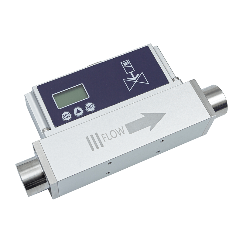
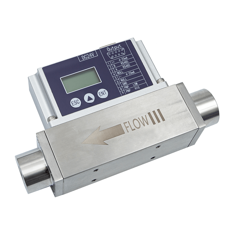
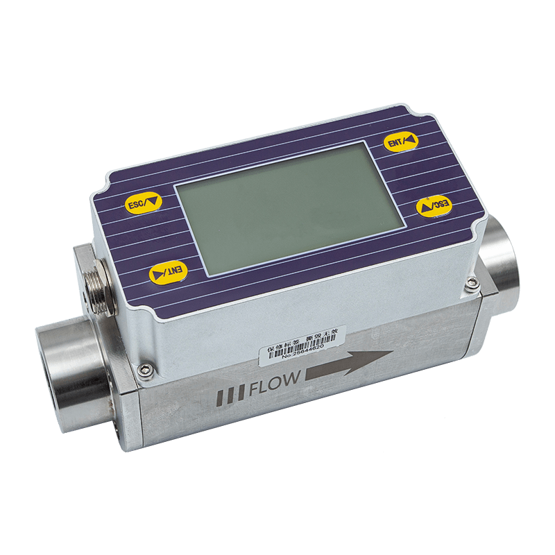
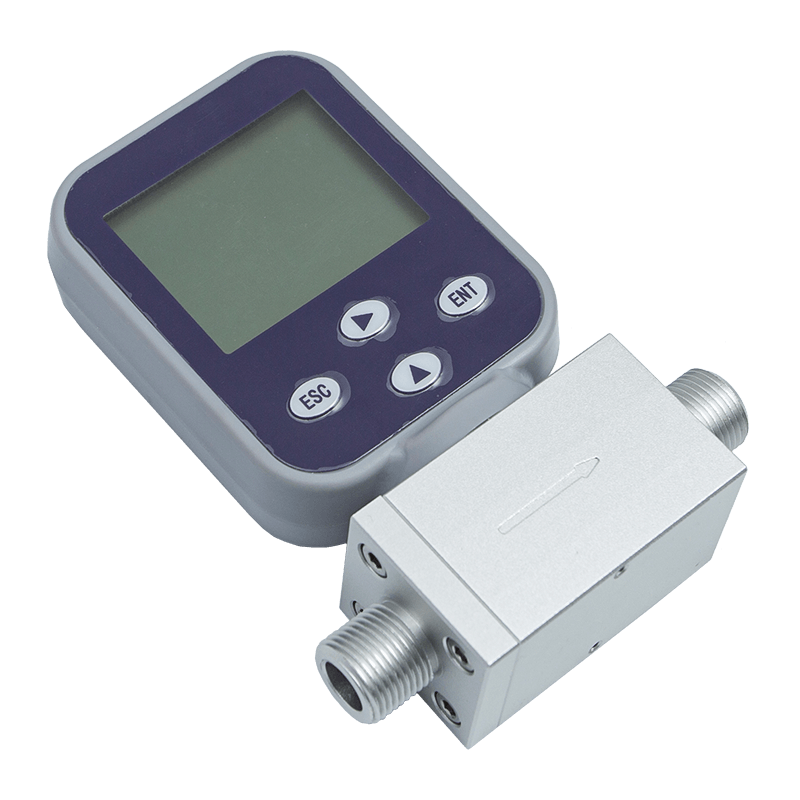
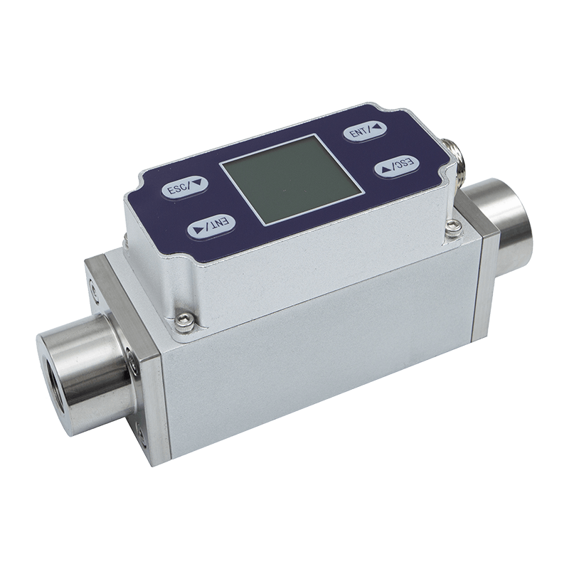
The AI-FK explosion-proof thermal gas mass flow meter is designed to address these requirements through a compact MEMS-based sensing system, digital communication, local display, standard industrial outputs, and an intrinsically safe explosion-proof design. It is intended for measuring and controlling various small-flow-rate clean gases without requiring conventional temperature and pressure compensation under its standard operating principle. The instrument can be used in process monitoring, gas distribution, laboratory and pilot equipment, energy management, equipment protection, and industrial automation.
With a measurement range from 0.3 NL/min to 3000 NL/min, an accuracy of ±1.5% FS, a response time of 50 to 1000 milliseconds, and optional temperature and pressure measurement functions, the meter provides a practical alternative to traditional volumetric and differential-pressure flow meters. Its 4–20 mA output, RS485 interface, MODBUS RTU protocol, LCD display, and configurable PNP output make it suitable for both standalone use and integration into modern industrial control systems.
Why Gas Flow Measurement Requires a Specialized Instrument
Gas behaves differently from liquids and presents several measurement challenges. Its density changes with temperature and pressure, its flow may be affected by installation conditions, and many industrial gas applications involve relatively low flow rates that are difficult to measure accurately with conventional instruments. A meter selected for liquid service or high-volume gas service may not provide sufficient sensitivity for small-flow applications.
In addition, industrial gas systems often require continuous monitoring rather than occasional manual inspection. A small deviation in gas flow may indicate leakage, blockage, valve failure, abnormal consumption, process instability, or equipment deterioration. For this reason, a modern gas flow meter should be able to provide real-time readings, cumulative totals, control outputs, and communication with a supervisory system.
Safety is another major consideration. Gas measurement equipment may be installed near fuel systems, chemical processes, coating lines, compressed gas equipment, or other areas where combustible substances can be present. In these environments, electrical equipment must be selected according to the applicable hazardous-area requirements. The AI-FK is developed as an intrinsically safe explosion-proof flow meter, allowing it to support measurement tasks where safety-oriented construction is required.
Measurement quality also depends on long-term stability. A flow meter that performs well during initial commissioning but experiences excessive zero drift can create false alarms, inaccurate consumption data, or unnecessary process adjustments. The AI-FK addresses this concern with a MEMS flow sensing chip, stable zero-point performance, and a specified zero drift of ±20 mV.
Product Overview
The AI-FK is an explosion-proof thermal gas mass flow meter for clean gases and small-flow-rate applications. It uses a microelectromechanical system flow sensing chip to detect gas flow through a thermal measurement principle. Because the instrument is based on mass-flow measurement, it is designed to reduce dependence on separate temperature and pressure compensation in standard applications.
The meter operates from a DC24V power supply with a rated consumption of 2.5 W. It provides a standard 4–20 mA current output for industrial control systems and an RS485 communication interface using the MODBUS RTU protocol. The built-in LCD can display both instantaneous flow and cumulative flow, giving operators access to live data at the installation point.
The output configuration can also include one PNP output. Depending on project requirements, this output may be supplied as a PNP pulse output or customized as a 0–5 V or 0–10 V voltage output. This flexibility enables the same basic instrument platform to serve different automation architectures.
Standard mechanical interfaces are available with BSPT internal thread and G internal thread options. These interfaces support practical installation into industrial piping and equipment. The meter is also available with customized temperature and pressure measurement functions when the application requires additional process information.
| Parameter | Specification | Application Value |
|---|---|---|
| Product type | Explosion-proof thermal gas mass flow meter | Gas measurement in industrial and potentially hazardous environments |
| Model | AI-FK | Compact platform for clean-gas flow monitoring |
| Power supply | DC24V, 2.5 W | Compatible with common industrial control power systems |
| Accuracy | ±1.5% FS | Suitable for process monitoring and control applications |
| Medium temperature | -10 to 50 °C | Supports ordinary industrial ambient and gas conditions within the stated range |
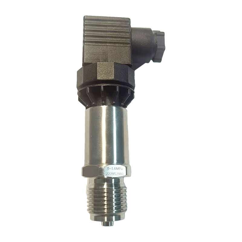
| Working pressure | Up to 1.6 MPa as standard | Suitable for many low- and medium-pressure gas systems |
| Minimum measurable flow | 0.3 NL/min | Supports sensitive low-flow monitoring |
| Maximum measurable flow | 3000 NL/min | Provides a broad selectable measurement range |
| Primary output | 4–20 mA | Direct connection to PLC, DCS, and data acquisition systems |
| Communication | RS485, MODBUS RTU | Digital networking and remote parameter access |
| Display | Instantaneous and cumulative flow | Local visual confirmation and basic consumption tracking |
| Response time | 50–1000 ms | Adaptable to monitoring and control requirements |
| Storage temperature | -10 to 65 °C | Supports practical transportation and storage conditions |
| Humidity | Below 95% RH, without frost or ice | Suitable for controlled industrial environments |
The stated reference conditions for measurement are 25 °C, 101.32 kPa, and dry air. Gas composition, installation conditions, pressure, temperature, and system cleanliness should be evaluated before final selection. When a project requires pressure ratings above the standard specification or integrated process sensing, the product can be customized subject to technical confirmation.
Explosion-Proof Type Thermal Gas Mass Flowmete
MEMS Thermal Sensing Technology
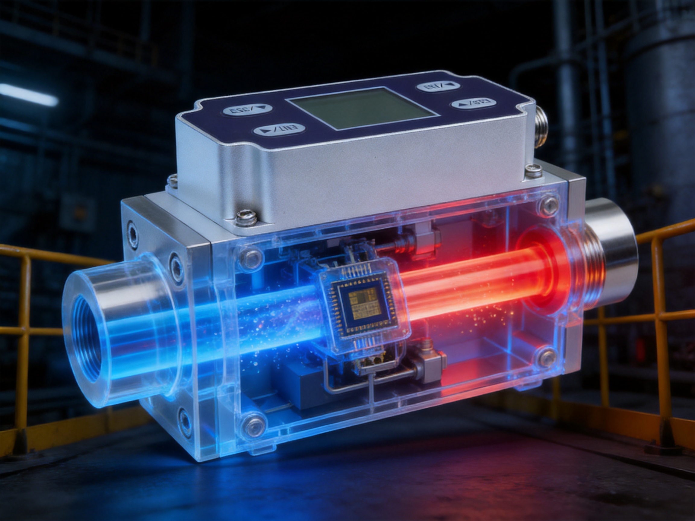
The core of the AI-FK is a MEMS flow sensing chip. MEMS technology uses micro-scale structures to create sensitive and repeatable sensing elements. In thermal gas measurement, the sensor detects the way moving gas carries heat away from a heated element. The relationship between heat transfer and gas movement allows the instrument to calculate flow.
A MEMS sensing structure can provide a high degree of sensitivity while remaining compact. This is particularly valuable in small-flow measurement, where the signal generated by the gas movement may be relatively weak. A sensitive sensor allows the meter to respond to low flow rates and detect changes that might be overlooked by larger or less responsive technologies.
The sensor is also designed with strong anti-interference capabilities. Industrial installations can contain electrical noise, vibration, switching equipment, electromagnetic fields, and changing operating conditions. Although every installation still requires appropriate wiring, grounding, and environmental control, a sensor with strong anti-interference performance can improve the reliability of the measured signal.
Another advantage of a thermal mass flow principle is that the measurement is related to gas mass movement rather than relying solely on a mechanical displacement or pressure difference. Traditional volumetric meters measure volume under a defined condition, while differential-pressure meters infer flow from pressure loss across a restriction. These approaches can be effective, but they may require additional compensation, moving parts, or carefully managed pressure conditions.
The AI-FK is designed to avoid the need for separate temperature and pressure compensation in its standard measurement application. This can simplify the system architecture and reduce the number of external instruments required. For applications in which pressure and temperature data are important for process analysis, integrated temperature and pressure functions can be customized.
Measurement Stability and Repeatability
Accuracy is only one part of flow-meter performance. A useful industrial meter must also provide repeatable results when the same operating condition occurs repeatedly. Good repeatability supports reliable alarms, consistent batch records, trustworthy energy reports, and stable automatic control.
The AI-FK is specified with an accuracy of ±1.5% FS. The designation FS refers to full scale, meaning that the accuracy value is related to the selected measurement span. Users should therefore select a suitable range rather than choosing an unnecessarily large range for a very small application. Proper range selection improves the practical resolution and helps the instrument deliver meaningful data throughout normal operation.
Zero-point stability is particularly important in low-flow systems. When the actual flow is zero, the instrument should remain close to its zero indication. Excessive zero drift may be interpreted as unwanted consumption or a false process signal. The AI-FK specifies zero drift of ±20 mV and is designed with stable sensor behavior to support dependable baseline measurement.
Repeatable measurement also helps maintenance teams identify gradual changes in the gas system. For example, a consistent rise in flow at a known valve position may suggest a leak or a change in equipment demand. A gradual reduction may indicate a blocked filter, restricted pipe, pressure problem, or declining supply capacity.
As with all flow meters, the stated performance depends on using the instrument within its specified conditions. The gas should be compatible with the meter, the piping should be clean, the installation should follow the recommended mechanical arrangement, and the operating pressure and temperature should remain within the applicable limits.
Explosion-Proof and Safety-Oriented Design
In a hazardous industrial environment, measurement equipment must be considered as part of the overall safety system. An explosion-proof or intrinsically safe instrument is not a substitute for proper area classification, ventilation, gas detection, electrical protection, and operating procedures. However, selecting a suitable certified instrument is a critical part of responsible system design.
The AI-FK is described as having intrinsically safe explosion-proof certification. Its development is based on explosion-proof requirements, with the objective of supporting measurement in harsh environments where safety is a primary concern. The exact installation method, certification scope, permitted gas group, temperature class, wiring arrangement, and associated protective equipment should always be verified against the product documentation and the requirements of the destination market.
A safety-oriented design can provide several practical benefits. It allows process engineers to place measurement closer to the point of use, reduces the need for long impulse lines associated with some differential-pressure systems, and supports direct monitoring of gas delivery equipment. A compact electronic flow meter can also make it easier to integrate safety alarms and shutdown logic into a broader control system.
For installation in a hazardous area, engineers should confirm the following items before purchase and commissioning:
• The hazardous-area classification and applicable national or international standards.
• The gas type, concentration range, ignition characteristics, and temperature requirements.
• The permitted ambient and medium temperature range.
• The maximum working pressure and mechanical connection specification.
• The requirements for barriers, isolators, grounding, cable glands, and wiring.
• The compatibility of the 4–20 mA, RS485, and PNP outputs with the control system.
• The inspection, calibration, and maintenance procedures required by the site.
These checks ensure that the flow meter is used as intended and that its safety characteristics are preserved throughout the life of the installation.
Advantages Compared with Traditional Flow Meters
Compared with Volumetric Flow Meters
Volumetric flow meters measure the volume of gas passing through the meter. Because gas volume changes with pressure and temperature, the measured volume may not directly represent the actual mass of gas unless reference conditions and compensation are carefully managed. In many applications, this requires additional temperature and pressure instruments or conversion calculations.
The AI-FK uses thermal mass flow measurement, which is intended to provide a more direct representation of gas mass movement under its specified conditions. This can simplify monitoring and reduce the number of external components. The absence of moving mechanical displacement elements may also reduce mechanical wear and support stable long-term operation.
Compared with Differential-Pressure Flow Meters
Differential-pressure flow meters use a restriction, such as an orifice plate or similar device, to create a pressure difference. The pressure difference is then used to calculate flow. These systems are well established, but they may produce permanent pressure loss, require impulse lines, and involve additional pressure transmitters and compensation calculations.
The AI-FK is designed as a compact inline instrument that does not require the same differential-pressure impulse arrangement. This may simplify installation and reduce the number of leak points in small gas systems. It can also be advantageous where preserving available pressure is important.
Compared with Mechanical Meters
Mechanical meters may use moving parts that are affected by wear, contamination, lubrication, vibration, and changes in gas quality. For clean gas applications, the MEMS-based design of the AI-FK can offer a compact alternative with high sensitivity and no traditional mechanical measuring mechanism.
Reduced mechanical complexity can also support easier maintenance. Instead of servicing multiple moving elements, maintenance teams can focus on sensor condition, electrical connections, communication performance, sealing, and calibration verification.
Compared with Basic Analog Sensors
A simple analog flow sensor may provide only one output signal. The AI-FK combines a 4–20 mA output with RS485 communication, local LCD indication, and an optional PNP output. This combination gives users multiple ways to access the same measurement data.
The analog output is convenient for established PLC and DCS systems. RS485 supports multidrop communication and digital data exchange. The display helps operators verify field conditions without opening a control cabinet. The configurable PNP output can be used for pulse counting, switching, or selected voltage signaling, depending on the project design.
Industrial Communication and Automation Integration
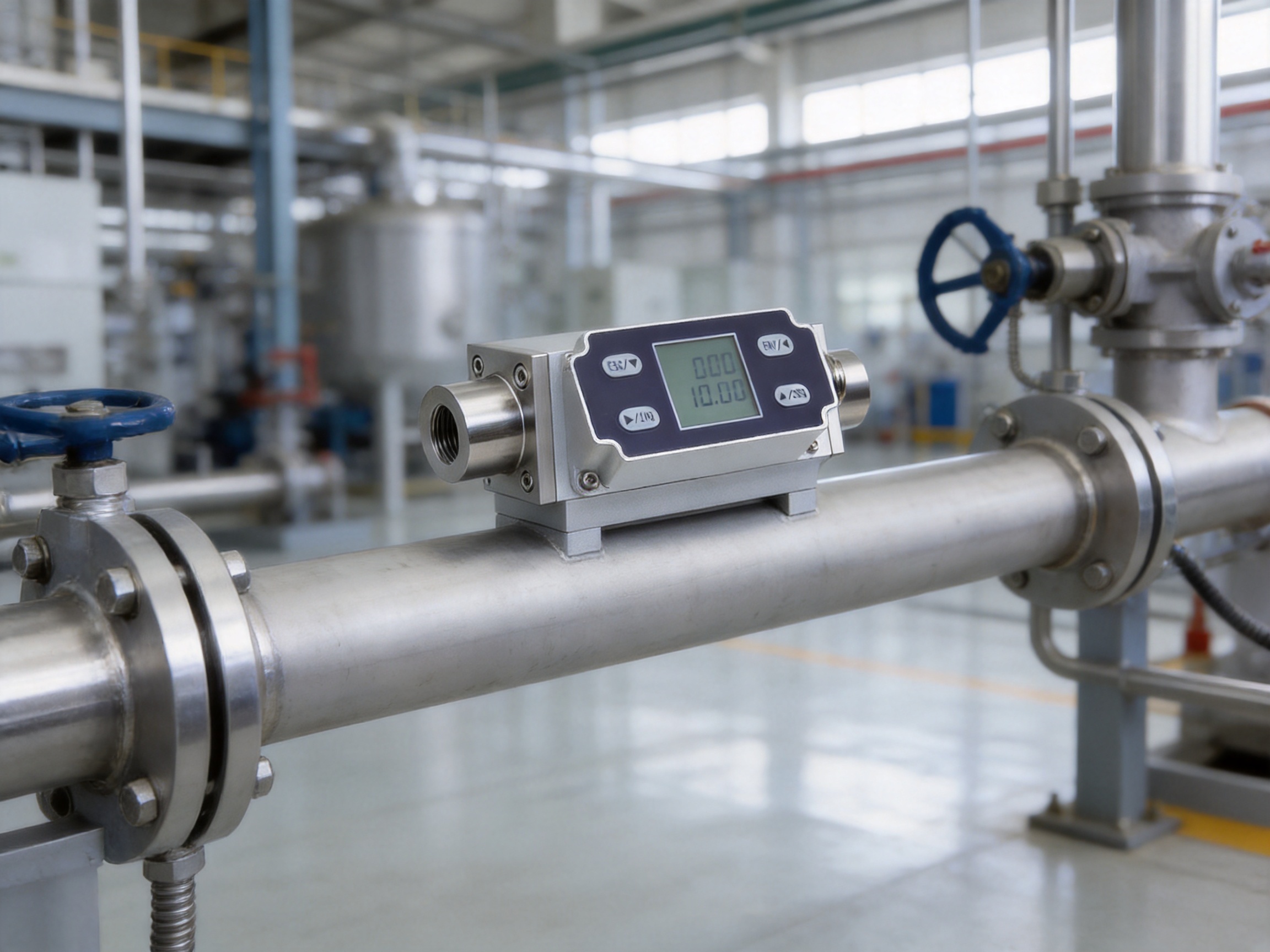
Modern flow measurement is increasingly connected to industrial automation. A meter should not only display flow locally; it should also communicate with control systems, gateways, data platforms, and plant-wide monitoring software. The AI-FK supports this approach through standard industrial interfaces.
The 4–20 mA output remains one of the most widely accepted signals in industrial automation. It can be transmitted over long distances and interpreted by PLC analog input modules, distributed control systems, remote I/O stations, and data acquisition equipment. The current-loop format also allows the control system to identify certain wiring or instrument faults when appropriate monitoring functions are configured.
The RS485 interface provides a digital communication path. Using MODBUS RTU, the flow meter can exchange data with a host controller, industrial computer, gateway, or monitoring platform. Digital communication can reduce the need for separate wiring for each parameter and can provide access to measured values, cumulative flow, status information, and other supported registers.
When integrating the meter into a network, system designers should define the communication address, baud rate, parity, stop bits, polling interval, cable topology, termination method, and grounding strategy. The final register map should be confirmed with the product documentation. Good network planning is essential when multiple devices share the same RS485 bus.
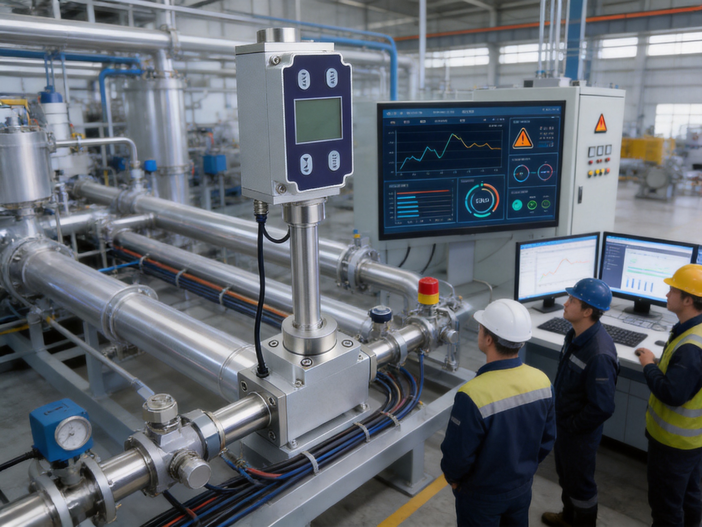
For an industrial IoT system, the flow meter can function as a field-level data source. A gateway may collect its values through MODBUS RTU and forward them to a supervisory platform using an industrial Ethernet or wireless protocol. This architecture can support dashboards, trend analysis, consumption reports, abnormal-flow alarms, and maintenance planning.
The company’s broader product portfolio includes broadband power line carriers, wireless temperature monitoring systems, industrial transmitters, flow meters, and automatic door controllers. This combination of sensing and communication products provides a foundation for integrated industrial data solutions. A plant can combine gas flow data with temperature, equipment condition, energy use, and access-control information to build a more complete view of operational performance.
Display, Outputs, and Operator Convenience
The integrated LCD displays instantaneous flow and cumulative flow. Instantaneous flow shows current gas movement and is useful for process adjustment, alarm response, and troubleshooting. Cumulative flow records the total amount measured over time and can support consumption management, production analysis, and cost allocation.
Local display capability is valuable during commissioning. Technicians can compare the meter indication with valve positions, pressure conditions, equipment status, and external test instruments. This reduces dependence on a remote control-room screen during installation and maintenance.
The 4–20 mA signal provides continuous process data, while the optional PNP output can be used for event-based control. For example, a pulse output may support totalizing equipment, and a switching signal may be used to indicate that a flow threshold has been reached. If a voltage output is preferred, 0–5 V or 0–10 V customization may be available.
These output options allow the AI-FK to fit both new and existing automation systems. A plant that already uses analog control can begin with 4–20 mA, while a more advanced installation can use RS485 for centralized data collection. The local display provides an additional layer of operational transparency.
Mechanical Installation and Piping Considerations
The AI-FK uses a standard mechanical interface and is available with BSPT internal thread and G internal thread options. Selecting the correct thread standard before ordering helps prevent installation delays and reduces the need for adapters.
Installation should be planned according to the gas type, pipe size, flow direction, available straight-run length, and the manufacturer’s mechanical interface requirements. The pipe should be clean and free from debris that could enter the sensor passage. Where the gas contains particles, a suitable filtration arrangement should be evaluated.
The flow meter should be mounted in a position that permits inspection of the display and access to the electrical connections. The installation should also protect the instrument from unnecessary vibration, water accumulation, corrosive exposure, and mechanical stress caused by unsupported piping.
Although the meter is designed for practical installation, good piping practice remains important. Sudden changes in pipe diameter, partially closed valves, sharp bends, regulators, and other disturbances can affect the flow profile. Where the application is sensitive, the piping layout should provide appropriate straight sections and stable operating conditions.
Before commissioning, the installer should check the mechanical connection, sealing method, flow direction, pressure rating, electrical polarity, communication wiring, grounding, and hazardous-area requirements. A controlled leak test should be conducted according to site procedures before the system is placed into normal service.
Applications Across Industrial Operations
Clean Gas Distribution
The AI-FK can be used to monitor gas supplied to production machines, test benches, laboratories, and process modules. Its broad range from 0.3 NL/min to 3000 NL/min makes it suitable for small gas branches as well as larger equipment lines, subject to correct model selection and operating conditions.
Leak Detection and Consumption Management
Unexpected gas consumption is often a sign of leakage, valve malfunction, or equipment left in an unintended operating state. By comparing instantaneous and cumulative flow with production schedules, operators can identify abnormal usage. Multiple meters installed at different branches can help isolate the location of a problem.
Process Control
Gas flow may influence combustion, purging, drying, coating, mixing, testing, or chemical processing. The 4–20 mA output can provide a process controller with continuous feedback. The response time of 50 to 1000 ms can be configured or selected according to whether the priority is rapid response or stable display behavior.
Hazardous Production Areas
The intrinsically safe explosion-proof design makes the AI-FK suitable for consideration in applications where gas safety is a primary concern. Examples may include gas supply skids, chemical production areas, fuel-handling systems, and industrial test environments. The site classification and certification details must be confirmed for each application.
Equipment Condition Monitoring
Gas flow can serve as an indirect indicator of equipment condition. A change in normal flow may reveal filter blockage, pressure instability, regulator failure, nozzle obstruction, or seal deterioration. When connected to an industrial monitoring platform, the meter can contribute to condition-based maintenance programs.
Energy and Carbon Management
Accurate gas data supports energy accounting and efficiency improvement. Cumulative flow records can be assigned to production lines, workshops, machines, or operating shifts. This helps organizations identify high-consumption equipment, compare production recipes, and evaluate the results of conservation measures.
Manufacturing and Engineering Strengths
A reliable flow meter depends not only on the sensing principle but also on the quality of engineering, assembly, testing, calibration, software, and technical support behind the product. ASY Electronics is a high-tech enterprise focused on smart-factory development, data sensing, intelligent connectivity, edge-layer hardware, and industrial data integration.
This product orientation is relevant to the AI-FK because a flow meter is increasingly used as part of a connected industrial system rather than as an isolated instrument. The company’s experience with industrial transmitters, wireless temperature monitoring, broadband power line carriers, and automatic door controllers provides a broader understanding of field devices, communication, and automation integration.
The company’s manufacturing strengths can be understood through several engineering priorities. First, the product is built around a specialized MEMS sensing chip rather than a generic mechanical mechanism. This requires attention to sensor integration, signal conditioning, calibration, and electrical stability.
Second, the instrument combines measurement and communication functions in one field device. The product must coordinate the sensor signal, display, analog output, digital communication, and optional switching or pulse output. Consistent firmware and hardware design are important to ensure that the values shown locally correspond with the values transmitted to the control system.
Third, explosion-proof equipment requires disciplined design and production control. Enclosure construction, electrical isolation, component selection, sealing, wiring, assembly, and inspection must be managed according to the applicable certification and quality requirements. These considerations are more demanding than those for a general-purpose indoor sensor.
Fourth, customization capability is an important manufacturing advantage. The AI-FK can be customized with integrated pressure measurement and display for higher pressure ratings, as well as temperature and pressure measurement functions. It can also support different mechanical connections and output configurations. Such flexibility allows the manufacturer to adapt the instrument to project-specific requirements rather than forcing every customer into one standard configuration.
Finally, the company’s smart-factory mission emphasizes efficient, reliable, and green digital productivity. This orientation supports the use of flow data for energy management, production optimization, and equipment monitoring. The product is therefore aligned with both measurement requirements and broader industrial digitalization goals.
Quality Control Priorities for a Thermal Gas Flow Meter
Quality control for this type of instrument should cover the complete product lifecycle. Incoming components must meet their technical specifications. The MEMS sensing chip, electronic components, display, connectors, enclosure materials, and mechanical interfaces must be checked for compatibility and consistency.
During assembly, attention should be given to sensor positioning, sealing, circuit-board mounting, connector reliability, and protection against contamination. Small particles or incorrect assembly can affect flow measurement, electrical safety, or long-term stability.
Calibration is another essential stage. The meter should be evaluated against controlled reference conditions, including the stated reference temperature, pressure, and dry-air condition where applicable. Calibration confirms the relationship between sensor response and displayed or transmitted flow.
Functional testing should verify the LCD, 4–20 mA output, RS485 communication, MODBUS RTU operation, and PNP or voltage output when configured. The instrument should also be checked for startup behavior, zero indication, response time, cumulative flow calculation, and alarm or threshold functions that are included in the selected configuration.
Safety-related products require additional attention to certification and traceability. Manufacturing records, inspection results, component substitutions, and production changes should be controlled carefully. Any customer purchasing the instrument for a hazardous area should request the current certification and technical documentation applicable to the intended installation.
Commissioning and Maintenance Recommendations
Before commissioning, confirm that the selected flow range matches the actual application. A meter that is oversized for the normal flow may provide less useful resolution, while a meter that is undersized may be exposed to conditions outside its intended range.
Verify that the gas is clean and compatible with the sensing path. If the gas contains dust, oil mist, condensate, or other contaminants, filtration or conditioning may be necessary. The meter should not be exposed to media outside the manufacturer’s stated application scope.
After installation, allow the system to stabilize before recording baseline data. Check the zero reading when the gas flow is shut off under safe conditions. Compare the local display with the control-system value and confirm that the 4–20 mA scaling is correct.
For RS485 installations, verify that the device address is unique and that the communication parameters match the host controller. Check the polarity of the RS485 wiring and ensure that the cable layout is appropriate for the network length and environment.
Routine maintenance should include visual inspection, checking for leakage, inspecting electrical connections, confirming display operation, reviewing diagnostic or communication status, and comparing readings with expected process conditions. The inspection interval should reflect gas cleanliness, operating severity, safety requirements, and the importance of the measurement.
If the gas system is modified, the meter should be re-evaluated. Changes in gas composition, pressure, temperature, pipe diameter, regulator configuration, or expected flow range may affect measurement performance. Calibration verification should be considered when the instrument is used for custody, billing, critical process control, or safety-related decisions.
How the Meter Supports Smart Factory Development
A smart factory depends on reliable information from the field. Sensors and transmitters provide the raw data needed for decisions about production, maintenance, quality, energy, and safety. The AI-FK can act as a field-level source of gas-flow data in this architecture.
At the equipment level, the meter measures and displays flow. At the control level, its analog and digital outputs connect to PLCs, DCS platforms, remote I/O, or industrial gateways. At the supervisory level, the collected data can be used for dashboards, reports, alerts, and trend analysis.
When combined with wireless temperature monitoring, industrial transmitters, power line communication, and other edge devices, gas flow can be correlated with equipment temperature, operating state, electrical consumption, and production output. This creates a more complete basis for identifying waste and improving asset performance.
For example, a plant may compare gas consumption with machine operating hours. If consumption continues while production is stopped, the system can generate an investigation alert. A rise in gas flow combined with abnormal temperature may indicate a process fault. A gradual reduction in flow combined with increased pressure drop may suggest filter blockage.
These use cases show why communication capability is an important competitive advantage. A meter that can be integrated directly into a data system provides more long-term value than a device used only for local indication.
Selection Guidance for Buyers and System Integrators
Before ordering, buyers should provide the manufacturer with the gas type, expected minimum and maximum flow, normal operating flow, pressure range, temperature range, pipe connection requirement, hazardous-area classification, output preference, and communication requirements.
The gas type is especially important. The AI-FK is designed for various small-flow-rate clean gases, but the suitability of any specific gas should be confirmed. Gas properties and composition can influence thermal measurement behavior and material compatibility.
The operating flow should be considered in relation to the available measurement range. The stated minimum measurable flow is 0.3 NL/min and the maximum is 3000 NL/min. Actual selection should account for startup flow, normal flow, peak flow, minimum stable flow, and the possibility of future process changes.
Pressure must also be confirmed. The standard working pressure is listed as no more than 1.6 MPa. Higher pressure ratings and integrated pressure measurement may be available through customization, but these requirements should be defined before production.
Mechanical connection standards should be selected carefully. BSPT internal thread and G internal thread are optional, and the connection dimensions should be reviewed against the existing piping or equipment interface.
Finally, the purchaser should identify whether the project needs only local display, 4–20 mA, RS485, MODBUS RTU, PNP pulse output, or a customized voltage output. Clear specification at the beginning reduces integration work and helps ensure that the delivered unit matches the control-system architecture.
Competitive Value of the AI-FK Platform
The AI-FK’s main competitive value comes from combining several capabilities in one compact instrument. MEMS sensing provides sensitivity and compactness. Thermal mass measurement reduces reliance on separate compensation in standard applications. Explosion-proof construction supports safety-oriented installations. Digital communication enables networking. Local display improves usability. Multiple outputs support compatibility with different automation systems.
Many competing products may offer one or two of these features, but the practical advantage of the AI-FK is the combination. A plant can obtain flow measurement, local indication, analog transmission, digital communication, and optional control output without installing several separate devices.
The broad flow range also supports different equipment scales. The low minimum flow specification is useful for small gas branches, while the upper range can serve larger industrial consumption points. Customization further improves the product’s suitability for specialized projects.
Cost efficiency is another consideration. A thermal flow meter that does not require a traditional differential-pressure assembly, external compensation instruments, or extensive impulse tubing may reduce installation complexity. Lower component count can shorten commissioning time and simplify maintenance, provided that the meter is correctly selected and installed.
For manufacturers and system integrators, the product also offers a practical platform for repeat projects. Standard interfaces, common industrial signals, and MODBUS RTU communication reduce the need to redesign the control architecture for every installation.
Q&A
What type of product is the AI-FK?
The AI-FK is an explosion-proof thermal gas mass flow meter designed for measuring and controlling various small-flow-rate clean gases in industrial applications.
What sensing technology does it use?
It uses a microelectromechanical system, or MEMS, flow sensing chip. The thermal sensing principle detects gas movement through heat-transfer behavior.
What is the specified accuracy?
The specified accuracy is ±1.5% FS. The practical result depends on correct range selection, installation, gas conditions, and operation within the specified limits.
What is the measurable flow range?
The minimum measurable flow rate is 0.3 NL/min, and the maximum measurable flow rate is 3000 NL/min. The appropriate range should be selected according to the actual gas and process conditions.
Does the meter require temperature and pressure compensation?
The standard product is designed to operate without separate temperature and pressure compensation for its intended measurement application. Temperature and pressure measurement functions can be customized when additional process data or higher-pressure capability is required.
What power supply is required?
The meter uses a DC24V power supply and has a rated power consumption of 2.5 W.
Which communication protocol is supported?
The meter supports RS485 communication using the MODBUS RTU protocol. Communication parameters and register details should be confirmed from the applicable technical documentation.
What outputs are available?
The standard output includes a 4–20 mA current signal. One PNP output is also available, and it may be configured as a pulse output or customized as a 0–5 V or 0–10 V output according to project requirements.
What information appears on the LCD?
The LCD displays instantaneous flow and cumulative flow. This allows operators to check current gas movement and accumulated consumption at the installation point.
What mechanical connections are offered?
BSPT internal thread and G internal thread options are available. The exact connection dimensions should be checked before ordering.
What is the standard working pressure?
The standard working pressure is no more than 1.6 MPa. Higher pressure ratings may be possible through customization with integrated pressure measurement and display, subject to technical confirmation.
Can it be installed in a hazardous area?
The product is described as having intrinsically safe explosion-proof certification and is designed for safety-oriented industrial environments. The purchaser must verify the certification scope, area classification, gas group, temperature class, and installation requirements for the specific site.
What gases can it measure?
It is intended for various clean gases, especially small-flow-rate applications. The exact gas type, composition, cleanliness, pressure, and temperature should be submitted for technical suitability confirmation before purchase.
What is the response time?
The stated response time is 50 to 1000 milliseconds. The suitable response setting depends on whether the application prioritizes rapid control response or smoother measurement presentation.
How does it compare with a differential-pressure meter?
It provides a compact thermal mass measurement solution without the same differential-pressure impulse-line arrangement. This can reduce installation complexity and pressure loss in suitable applications.
How does it support industrial IoT?
Its 4–20 mA and RS485 MODBUS RTU interfaces allow connection to PLCs, DCS systems, gateways, and industrial data platforms. Flow data can be used for energy management, equipment monitoring, alarms, and production analysis.
What should be confirmed before ordering?
The buyer should confirm gas type, flow range, pressure, temperature, pipe connection, hazardous-area requirements, power supply, output configuration, communication parameters, display requirements, and any need for customized temperature or pressure measurement.
Conclusion
The AI-FK explosion-proof thermal gas mass flow meter is designed for industrial users who need accurate, stable, connected, and safety-oriented gas measurement. Its MEMS sensing chip provides high sensitivity and compact construction, while the thermal mass principle supports measurement without separate compensation in standard applications.
The combination of ±1.5% FS accuracy, low-flow measurement capability, stable zero performance, 4–20 mA output, RS485 MODBUS RTU communication, LCD indication, configurable PNP output, and optional temperature and pressure functions gives the meter broad application value.
Compared with traditional volumetric, differential-pressure, mechanical, or basic analog instruments, it can reduce system complexity and improve access to real-time industrial data. Its standard interfaces make it suitable for integration into existing automation systems, while its customization options support more specialized installations.
Backed by ASY Electronics’ focus on industrial sensing, intelligent connectivity, edge hardware, and smart-factory solutions, the product is positioned not merely as a flow indicator but as a field device for connected industrial operations. When correctly selected, installed, and maintained, it can support safer gas handling, more reliable process control, improved consumption visibility, and data-driven factory improvement.
References
1. Product technical information for the AI-FK explosion-proof thermal gas mass flow meter, including operating specifications, outputs, communication functions, and installation options.
2. General principles of thermal mass flow measurement and MEMS-based gas sensing technology.
3. Industrial instrumentation practices for 4–20 mA signal transmission and RS485 MODBUS RTU communication.
4. Hazardous-area equipment selection principles for intrinsically safe and explosion-proof industrial instruments.
5. Industrial process measurement and control engineering practices for gas flow monitoring.
6. Smart-factory engineering concepts related to edge sensing, industrial communication, energy management, and equipment condition monitoring.
7. Manufacturer-provided company information concerning industrial IoT communication solutions, sensing products, transmitters, flow meters, and intelligent connectivity.