

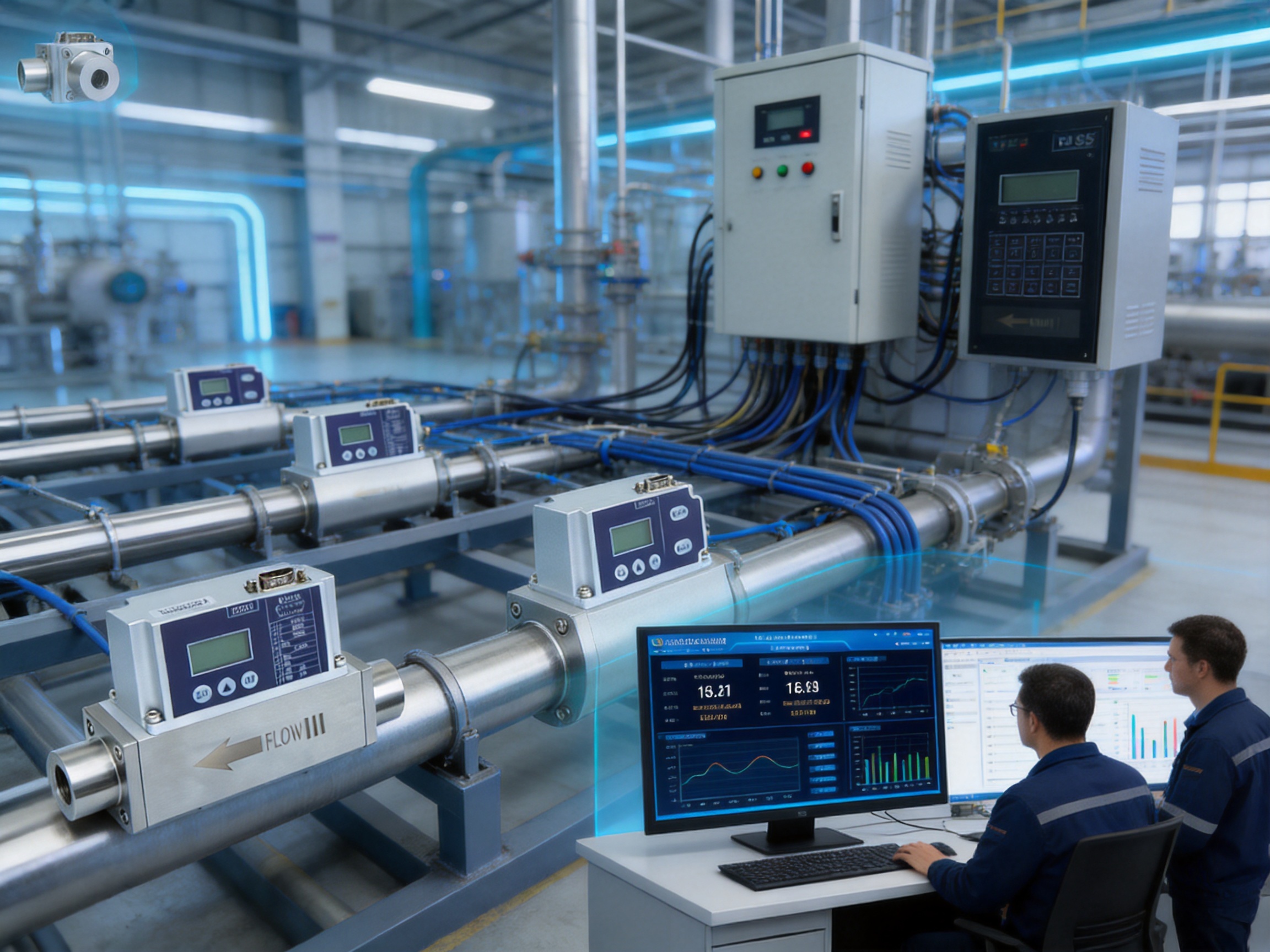
Accurate gas measurement is essential wherever industrial processes depend on stable flow, repeatable dosing, controlled combustion, leak detection, laboratory gas delivery, or energy-efficient operation. Even a small measurement error can influence product quality, operating cost, equipment safety, and regulatory performance. For this reason, modern facilities increasingly require flow meters that can measure low gas flow rates with fast response, strong repeatability, simple installation, and reliable communication with automation systems.
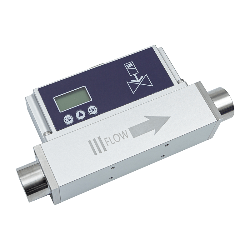
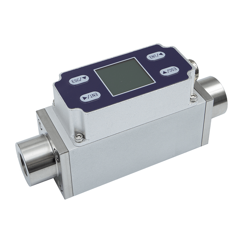
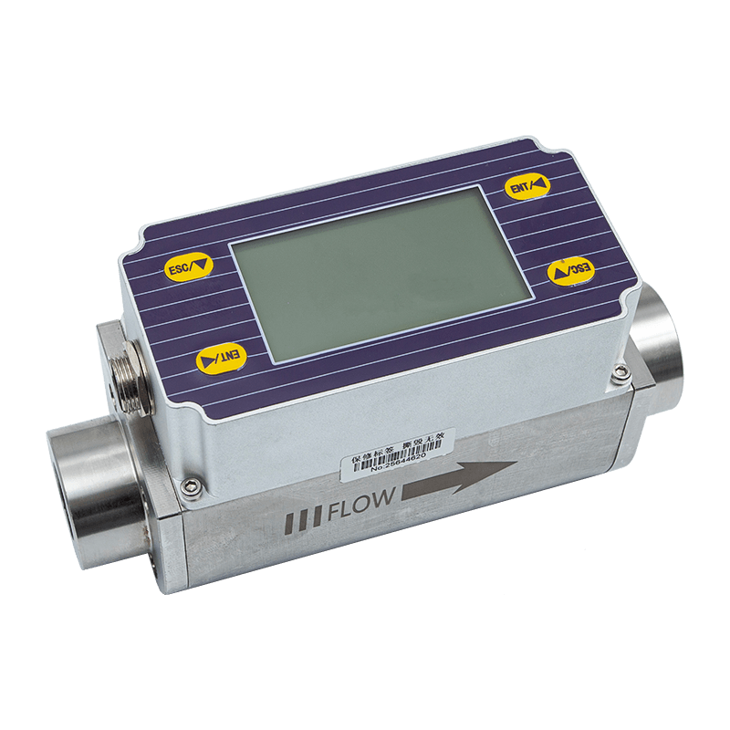
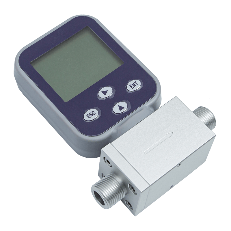
The AI-FM high-precision thermal gas mass flow meter is designed for these requirements. It uses an advanced microelectromechanical system, or MEMS, flow sensing chip to measure small flows of clean gases with high sensitivity. The instrument combines thermal mass measurement, digital processing, local display, industrial signal outputs, and RS485 communication in a compact solution intended for demanding industrial and technical applications.
Unlike conventional volumetric or differential-pressure instruments, the meter measures gas mass flow thermally and does not require separate temperature or pressure compensation under its intended operating conditions. This reduces system complexity and can simplify installation, commissioning, and maintenance. The meter also provides a wide 1:100 range ratio, a response time of approximately 50 milliseconds, selectable output options, and support for multiple gases.
Its performance is further supported by the engineering capabilities of ASY Electronics, a high-tech manufacturer focused on data sensing, intelligent connectivity, industrial transmitters, flow meters, wireless monitoring systems, broadband power line communication products, and automatic door controllers. The company’s emphasis on self-developed edge-layer hardware and industrial data integration enables the meter to function not only as a standalone instrument, but also as a practical sensing element within a connected industrial system.
1. The Role of Precise Gas Measurement in Modern Industry
Gas flow measurement is used in many processes that appear simple but require carefully controlled operating conditions. Examples include laboratory gas supply, semiconductor and electronics manufacturing, fuel and combustion control, environmental equipment, analytical instruments, medical and technical gas distribution, pneumatic systems, and process equipment that uses nitrogen, oxygen, hydrogen, carbon dioxide, or other gases.
In low-flow applications, measurement challenges become more significant. The flow may change quickly, the available installation space may be limited, and the difference between normal and abnormal operation may be very small. A sensor must therefore detect low flow rates while maintaining stable zero-point performance. It must also reject electrical and environmental interference so that the output remains trustworthy in an industrial installation.
Traditional flow technologies can require additional instruments or calculations. Volumetric meters may need correction for temperature and pressure. Differential-pressure flow meters generally require a pressure drop, a carefully designed primary element, and additional compensation when process conditions change. These requirements can increase the size, cost, and maintenance burden of the complete measurement system.
A thermal gas mass flow meter approaches the problem differently. It uses the relationship between heat transfer and moving gas to determine mass flow. Because the sensing principle responds to the mass movement of the gas, the instrument is well suited to clean-gas applications where low flow sensitivity and a broad measurement range are more important than creating a large pressure loss.
2. Product Overview
The AI-FM is a high-precision thermal gas mass flow meter developed around a MEMS flow sensing chip. MEMS technology enables the sensing structure and related thermal elements to be produced in a small, consistent, and highly sensitive format. The resulting sensor can detect changes in gas flow with a fast response and can support accurate measurement across a broad operating range.
The meter is designed for clean gases and can be configured for air, nitrogen, oxygen, methane, argon, carbon dioxide, helium, hydrogen, and propane. Other gas types may be available through manufacturer configuration. Gas selection is important because thermal properties vary from one gas to another. Correct configuration helps the instrument translate the thermal response of the sensing element into an accurate flow reading.
The device supports instantaneous and cumulative flow display. This allows operators to observe current process behavior while also tracking total consumption over time. The local LCD display makes the instrument useful during commissioning, routine inspection, troubleshooting, and field service, even when a supervisory control system is not immediately accessible.
For integration with control equipment, the meter can provide a 4–20 mA current signal or a selectable voltage output of 1–5 V, 0–5 V, or 0–10 V. RS485 communication using the Modbus RTU protocol is also available. A PNP output can be selected for applications that require a switching signal, alarm trigger, or simple control interface.
The product is available with DN8 and DN15 pipe diameters. Standard mechanical connections include PT1/2 or G1/4 internal threads, while other thread interfaces can be customized. This flexibility helps engineers match the meter to existing piping, manifolds, regulators, and equipment layouts.
| Parameter | Specification |
|---|---|
| Product type | High-precision thermal gas mass flow meter |
| Model description | AI-FM |
| Power supply | DC24V / 2.5W |
| Accuracy | ±1.0% FS |
| Response time | Approximately 50 ms |
| Measurement range ratio | 1:100 |
| Minimum measurable flow | 0.3 NmL/min |
| Maximum measurable flow | 1000 NL/min |
| Medium temperature | -10 to 55 °C |
| Storage temperature | -10 to 65 °C |
| Maximum standard working pressure | ≤1.5 MPa |
| Optional pressure customization | Up to 3 MPa, subject to configuration |
| Humidity | Below 95% RH, without frost, ice, or condensation |
| Outputs | 4–20 mA, 1–5 V, 0–5 V, or 0–10 V |
| Communication | RS485, Modbus RTU |
| Display | Instantaneous flow and cumulative flow |
| Protection rating | IP40 |
| Gas options | Air, N2, O2, CH4, Ar, CO2, He, H2, and C3H8 |
Unless otherwise specified, the stated flow performance is measured at 25 °C, 101.32 kPa, and in dry air. Users should confirm the selected gas, reference conditions, pressure, temperature, pipe configuration, and desired output range before ordering.
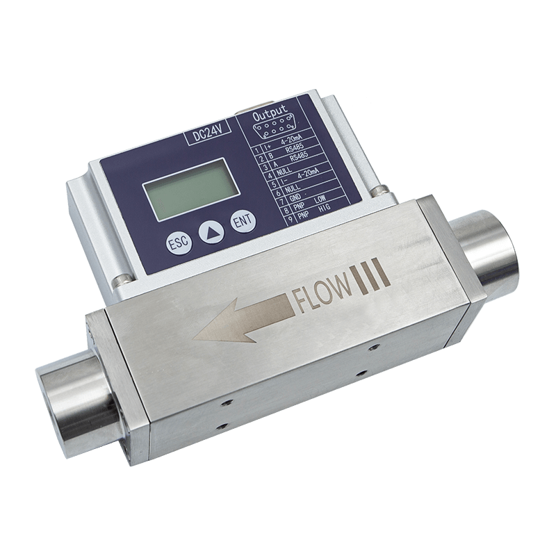
High-Precision Type Thermal Gas Mass Flowmete
3. MEMS Thermal Sensing for High Sensitivity
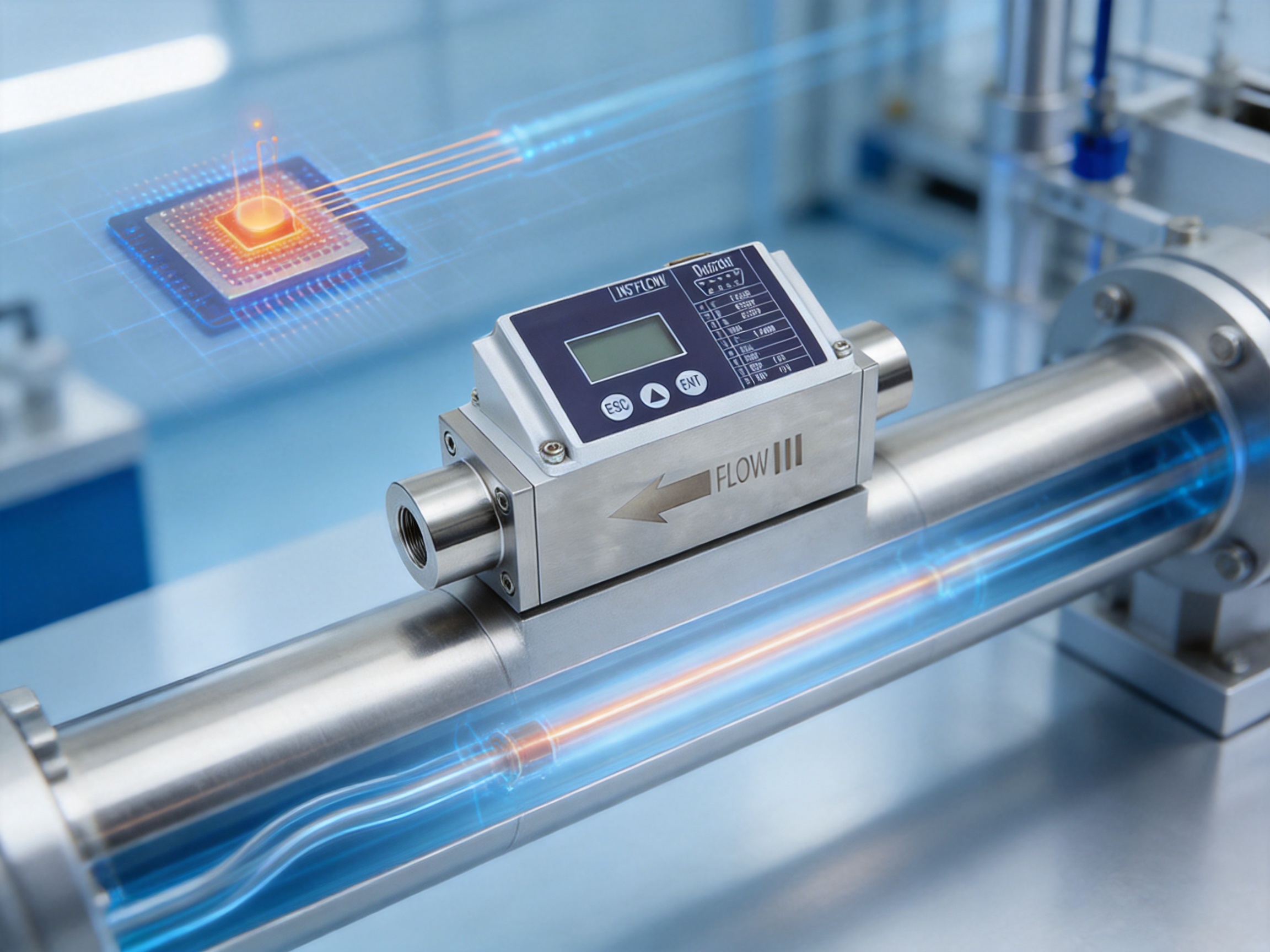
The central advantage of this meter is its MEMS-based flow sensing chip. MEMS technology combines mechanical structures, thermal elements, and electronic functions at a very small scale. This makes it possible to create a sensing element with a low thermal mass and a rapid response to changing flow conditions.
In a thermal flow sensor, a controlled heating element introduces a small amount of heat into the gas stream. As gas passes the heated area, it carries heat away. The rate and distribution of heat transfer vary with gas movement. The electronic circuit measures the thermal effect and converts it into a flow value through calibration and signal processing.
A MEMS structure can place the heater and temperature-sensitive elements in a carefully controlled relationship. This helps improve sensitivity to low flow and supports a compact sensor design. It also enables consistent production of the sensing structure when suitable manufacturing controls are applied.
For industrial users, the benefit is not simply a smaller sensor. The combination of low-flow sensitivity, fast thermal response, and digital signal processing allows the instrument to identify changes that may be difficult to detect with larger or less sensitive technologies. This is especially valuable in small-pipe installations, gas consumption monitoring, laboratory equipment, and process systems where the available flow signal is limited.
3.1 Stable Zero-Point Performance
Zero-point stability is an important consideration in low-flow measurement. When the actual flow is near zero, even a small electrical drift or thermal disturbance can create a misleading reading. A stable zero point helps distinguish genuine gas movement from sensor offset and environmental influence.
The AI-FM is designed with attention to sensor zero-point stability. In practical operation, this supports more dependable monitoring of standby conditions, leakage, intermittent flow, and low-consumption processes. Stable zero behavior also reduces the need for frequent manual correction and makes automated alarm thresholds more meaningful.
3.2 Accuracy and Repeatability
The specified accuracy is ±1.0% of full scale. This rating should be interpreted together with the selected range, gas type, reference condition, installation arrangement, and application environment. Within the suitable measurement range, the meter is designed to provide high accuracy and good repeatability.
Repeatability is particularly important when the instrument is used for process control. An operator may not need to know only the absolute flow value; the operator may also need to identify whether the same operating command produces the same result from one production cycle to the next. Consistent measurement supports process comparison, preventive maintenance, and quality analysis.
For energy management, repeatable readings make it easier to identify abnormal consumption. A change in flow may indicate a leak, a blocked filter, a regulator problem, a valve that does not close completely, or an unexpected change in production demand. The meter can therefore contribute to both process optimization and equipment diagnostics.
4. Advantages Compared with Conventional Flow Technologies
Every flow technology has an appropriate operating range. The value of the AI-FM lies in the combination of features it provides for clean-gas, low-flow, and connected industrial applications.
4.1 No Separate Temperature or Pressure Compensation Required in the Intended Application
Conventional volumetric flow measurement often requires the user to compensate the reading when gas temperature or pressure changes. A thermal mass flow meter directly responds to gas mass movement under its calibrated conditions, reducing the need for a separate temperature and pressure compensation system in many applications.
This does not mean that operating conditions can be ignored. Users must still select the correct gas and remain within the specified temperature and pressure limits. However, the system can be simpler because it does not necessarily require additional pressure and temperature transmitters solely to calculate a corrected mass flow value.
4.2 Low Pressure Drop
Many differential-pressure flow meters use an orifice, nozzle, or similar restriction to create a measurable pressure difference. That restriction can produce permanent pressure loss and may require larger upstream and downstream straight-run sections. The thermal sensing approach can measure flow without relying on a large artificial pressure drop, which is useful when the available supply pressure is limited.
Lower pressure loss can support more efficient gas distribution and reduce the need for oversized compressors, regulators, or pressure recovery arrangements. It can also be beneficial in laboratory and instrument systems where stable pressure is important.
4.3 Wide Measurement Range
The 1:100 range ratio gives the meter a broad usable span between low and high flow conditions. This is advantageous where demand changes during a production cycle or where one instrument must monitor both standby consumption and normal operation.
A broad range can reduce the need to install separate meters for different operating states. It also improves the possibility of selecting a practical instrument for variable-demand equipment. Engineers should nevertheless confirm the required minimum and maximum flow before final selection, because range ratio does not replace correct sizing.
4.4 Fast Response
With a response time of approximately 50 milliseconds, the meter can follow rapid flow changes. Fast response is valuable for valve actuation, pulsed gas delivery, burner control, leak detection, and process sequences where a delayed reading could affect control quality.
Rapid measurement also improves troubleshooting. When a valve opens, closes, or partially obstructs a line, the change can be observed quickly on the local display or through the control system. This helps maintenance personnel compare commanded behavior with actual gas movement.
4.5 Multiple Industrial Interfaces
Different facilities use different control architectures. Some require a traditional 4–20 mA signal, some use voltage input cards, and others prefer digital communication. The available interfaces allow the meter to fit into a broad range of control systems without requiring an external signal converter in every case.
RS485 with Modbus RTU is especially useful in distributed industrial installations. A control system can collect instantaneous flow, cumulative flow, status information, and other available values over a communication network. Digital networking can reduce point-to-point wiring and support centralized data analysis.
4.6 Local Display and Remote Data
A local display and remote communication serve different purposes. The display gives technicians immediate access to the reading at the installation point. The communication interface allows the same measurement to be monitored from a control cabinet, operator station, or industrial data platform.
Having both options improves commissioning efficiency. A technician can verify local operation while an automation engineer checks the value received by the controller. This makes it easier to identify wiring errors, scaling problems, address conflicts, or incorrect configuration.
5. Gas Compatibility and Measurement Configuration
The instrument can be configured for several common gases, including air, nitrogen, oxygen, methane, argon, carbon dioxide, helium, hydrogen, and propane. These gases are used in laboratories, welding and cutting, combustion systems, analytical equipment, process manufacturing, and energy applications.
Thermal measurement depends on the thermal properties of the gas. A sensor calibrated for air should not automatically be assumed to provide the same accuracy when used with hydrogen or carbon dioxide. The selected gas must therefore be specified correctly during configuration. Where a less common gas is required, users should consult the manufacturer before purchase.
Gas cleanliness is also important. The product is intended for clean-gas measurement. Particles, oil, liquid droplets, condensation, or chemical contamination may affect the sensing surface and lead to incorrect measurement or long-term reliability problems. Appropriate filtration, drying, and upstream system design should be considered for demanding applications.
Oxygen and combustible gases require additional attention to system safety. Materials, seals, installation practices, electrical classification, and operating procedures must be suitable for the gas and the site. The product information identifies intrinsic safety and explosion-proof certification as available safety characteristics, but the end user must verify the exact certification, configuration, and local installation requirements before use in a hazardous location.
6. Industrial Applications
6.1 Factory Energy Management
Compressed air and industrial gases can represent a significant operating cost. A flow meter installed on a branch line or machine supply can reveal how much gas is consumed during production, idle periods, cleaning cycles, or shift changes.
By comparing flow with production output, a factory can calculate consumption per unit and identify opportunities for improvement. Unexpected nighttime or weekend flow may indicate leaks or equipment that has not been shut down. Because the meter provides cumulative flow as well as instantaneous flow, it can support both real-time supervision and longer-term energy analysis.
6.2 Pneumatic Equipment Monitoring
Pneumatic cylinders, actuators, grippers, and control systems often depend on stable compressed-air delivery. A flow meter can be used to observe demand, identify leakage, and verify that equipment receives the expected supply.
A sudden increase in flow may indicate a damaged tube, deteriorated seal, or valve malfunction. A lower-than-expected flow may point to a clogged filter, restricted tubing, pressure regulator issue, or incomplete valve opening. Integrating the meter into an equipment monitoring system can help maintenance teams move from reactive repair to condition-based maintenance.
6.3 Laboratory and Analytical Equipment
Laboratory instruments frequently use small quantities of gases and require accurate, repeatable delivery. The low minimum measurable flow and high sensitivity of the MEMS sensor make this type of meter suitable for selected clean-gas laboratory systems, provided the gas, pressure, materials, and cleanliness requirements are compatible.
The compact mechanical connections and selectable output signals can simplify integration into test benches, gas mixing equipment, calibration systems, and analytical platforms. The local display is also useful when a laboratory technician needs to verify flow without opening a software interface.
6.4 Combustion and Fuel Systems
Gas flow affects the air-to-fuel ratio, combustion stability, emissions, and energy efficiency of many systems. A fast-response flow signal can support monitoring and control of fuel or combustion-support gases.
For combustible gases such as methane, hydrogen, or propane, application engineering must include appropriate safety controls. The instrument should be selected and installed according to the gas properties, hazardous-area classification, pressure conditions, and applicable regulations. The meter can provide useful measurement data, but it must be part of a complete engineered safety system.
6.5 Gas Distribution and Process Skids
Gas distribution panels and process skids often require several compact measurement points. The AI-FM’s available pipe sizes, internal thread options, digital communication, and analog outputs support flexible skid design.
Multiple meters can be connected to a supervisory system for centralized monitoring. This is useful when a facility must compare consumption across production lines, gas types, or process stages. A common communication architecture also makes future expansion easier when additional measurement points are added.
6.6 Equipment Condition Monitoring
Gas flow is often an indirect indicator of equipment condition. Changes in normal flow behavior can show that a pump, valve, regulator, filter, actuator, or process chamber is operating differently from its established baseline.
When flow data is combined with pressure, temperature, production status, and alarm information, it becomes a valuable input for industrial analytics. This aligns with the broader development of intelligent manufacturing, where data from edge devices is used to improve reliability, quality, energy efficiency, and production planning.
7. Engineering and Manufacturing Strengths
The performance of a precision flow meter depends on more than the sensing principle. Sensor design, electronic integration, calibration, mechanical quality, software configuration, inspection, and application support all influence the final result. ASY Electronics operates as a high-tech enterprise focused on data sensing and intelligent connectivity, providing a foundation for the development of industrial measurement products.
7.1 Self-Developed Edge-Layer Hardware
Industrial sensors operate at the edge of a production system. They interact directly with gas lines, machines, controllers, and field technicians. Self-developed edge-layer hardware enables the manufacturer to coordinate the sensing element, signal conditioning, communication interface, local display, and mechanical package as a complete product rather than treating each component as an isolated part.
This integrated approach can improve compatibility between hardware and software. It also makes it easier to tailor output options, communication behavior, gas configuration, display functions, and mechanical interfaces to practical industrial requirements.
7.2 Integration of Sensing and Connectivity
The company’s product portfolio includes thermal gas mass flow meters, industrial transmitters, wireless temperature monitoring systems, broadband power line communication equipment, and automatic door controllers. Although these products serve different applications, they share a common foundation: collecting field data and transmitting it reliably to a control or management system.
This experience with intelligent connectivity is valuable for flow-meter development. A modern measurement instrument must not only sense accurately; it must also communicate consistently, coexist with other devices, and provide usable information to a wider industrial platform.
7.3 Calibration-Oriented Product Development
Thermal mass flow instruments require careful calibration because the output depends on gas properties, reference conditions, sensing characteristics, and electronic processing. A professional manufacturing process should include controlled calibration, comparison against reference instruments, adjustment of output scaling, and verification of communication values.
For customers, this means that product quality is influenced by the full calibration workflow, not only by the nominal sensor specification. Configuration for the selected gas and range helps ensure that the instrument is appropriate for the intended installation.
7.4 Mechanical and Electrical Flexibility
Industrial equipment is rarely standardized across every facility. Thread requirements, pipe diameter, signal type, supply voltage, enclosure arrangement, and controller compatibility can vary significantly. The availability of PT1/2 and G1/4 internal threads, optional signal outputs, RS485 communication, and customized interfaces helps reduce the need for extensive field modification.
Manufacturing flexibility also supports OEM and system-integrator projects. A flow meter can be incorporated into a skid, cabinet, laboratory instrument, energy-management package, or machine-monitoring system while retaining a consistent measurement platform.
7.5 Quality Control and Application Support
A strong industrial manufacturer must consider quality at several stages: incoming component inspection, sensor assembly, circuit-board production, mechanical assembly, firmware configuration, calibration, finished-product testing, packaging, and after-sales technical support.
Application support is equally important. Customers need assistance with gas selection, flow-range selection, installation orientation, signal wiring, Modbus communication, reference conditions, and operating limits. Clear technical guidance reduces commissioning time and helps prevent avoidable measurement errors.
8. Installation Recommendations
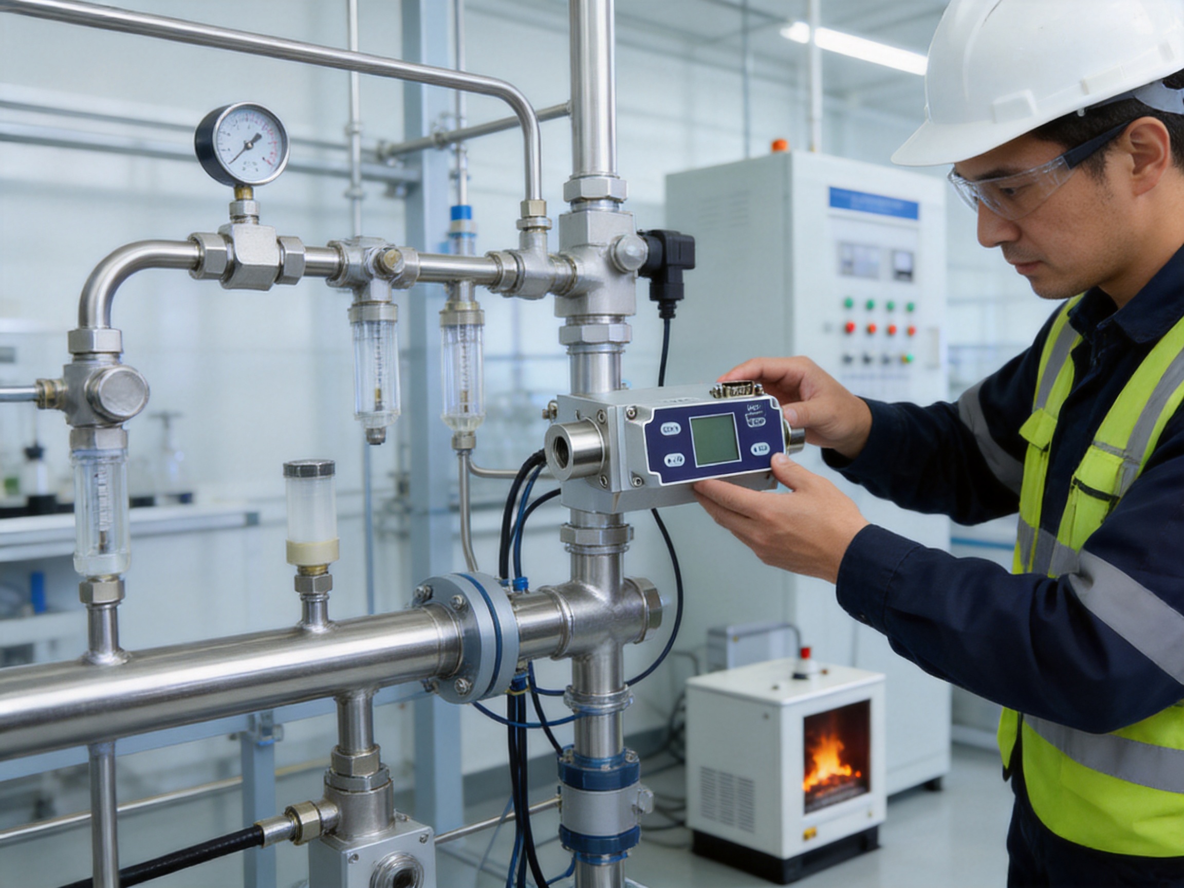
Correct installation is essential for achieving the stated performance of any flow meter. Before installation, confirm that the selected meter matches the gas type, maximum pressure, temperature range, pipe diameter, thread specification, and expected minimum and maximum flow.
The piping should be clean and free from debris, oil, moisture, and loose sealing material. If the gas may contain particles or liquid, suitable filtration or separation should be installed upstream. Condensation should be prevented because the product is specified for conditions without frost, ice, or condensation.
Installers should avoid mechanical stress on the meter body. Piping should be properly supported so that the instrument is not used as a structural connection point. Thread sealant should be applied carefully to prevent material from entering the gas passage. The sealant must also be compatible with the gas and operating temperature.
Flow direction should follow the marking or installation instructions supplied with the instrument. Unnecessary turbulence, sudden contractions, sharp bends, partially closed valves, and poorly positioned regulators near the sensor may influence the flow profile. Where the application requires high accuracy, the designer should follow recommended upstream and downstream straight-pipe conditions.
The meter uses DC24V power with a rated consumption of approximately 2.5 W. The power supply should be stable and correctly wired. Signal cables should be routed in a way that limits interference from motors, variable-frequency drives, contactors, and high-power switching equipment.
For RS485 installations, observe correct polarity, network topology, termination practices, device addressing, and baud-rate settings. Modbus RTU networks should be configured consistently across all connected devices. Shielding and grounding should be implemented according to the site’s electrical design and safety requirements.
9. Commissioning and Operation
After installation, inspect all mechanical connections and confirm that the gas line is leak-free. Verify the power supply before energizing the instrument. The recommended preheating time is approximately three to four minutes for best results. This allows the sensor and electronics to reach a stable operating condition before demanding the highest measurement accuracy.
During commissioning, confirm that the displayed gas type, reference temperature, flow unit, output range, and communication parameters match the application. The selectable standard temperature conditions are 0 °C, 20 °C, and 25 °C, with 25 °C as the default. The selected reference condition should be consistent with the requirements of the process and the rest of the measurement system.
Observe the zero-flow reading when the line is isolated and confirmed to be free of movement. The zero value should be stable within the expected instrument behavior. If the reading is abnormal, check for leakage, residual flow, pressure fluctuations, condensation, wiring problems, or incorrect configuration before attempting any adjustment.
Test the analog output against the controller input and confirm that the scaling is correct. For example, a control system must know which flow value corresponds to the lower and upper limits of the selected 4–20 mA or voltage range. Digital communication should be tested using the correct device address and register information.
Do not exceed the specified measurement range. The product documentation specifically warns that exceeding the range may damage the sensor. If process demand can temporarily exceed normal operating flow, select a suitable range or add an appropriate protective design rather than relying on occasional overload tolerance.
10. Maintenance and Long-Term Reliability
Thermal flow meters generally have no moving mechanical measurement parts, which can reduce mechanical wear compared with some traditional meter designs. Nevertheless, reliable long-term operation still depends on clean gas, suitable environmental conditions, stable power, and periodic verification.
Inspect the installation for leakage, vibration, corrosion, condensation, and cable damage. Check whether filters or upstream components require service. If the gas supply changes, confirm that the meter is still configured for the correct gas. A change from air to nitrogen, for example, should not be treated as a minor adjustment because the thermal response is gas dependent.
Use the local display and communication data to establish a normal operating baseline. Maintenance personnel can compare current flow with historical values and investigate gradual changes. A slow increase in cumulative consumption or a higher standby flow may indicate a developing leak or equipment degradation.
Calibration intervals depend on the application, gas cleanliness, operating conditions, required accuracy, and quality system. Facilities with strict measurement requirements should establish a verification schedule based on risk and process importance. Calibration or service should be performed by qualified personnel using suitable reference equipment.
If the instrument is removed from service, protect the mechanical connections and prevent contaminants from entering the gas passage. Store it within the specified storage temperature range of -10 to 65 °C and avoid moisture, condensation, impact, and aggressive chemicals.
11. Integration into Industrial IoT Systems
The meter can function as a field-level data source within an industrial Internet of Things architecture. At the device level, it measures flow and presents the value through the display or electrical interface. At the control level, a PLC, remote I/O unit, gateway, or industrial computer can collect the data. At the management level, software can analyze consumption, alarms, production relationships, and equipment performance.
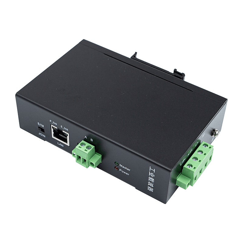
RS485 and Modbus RTU make the instrument suitable for many distributed monitoring systems. A gateway can collect data from multiple meters and forward it to a supervisory platform. This can reduce manual readings and create a more complete record of gas usage.
Data from the flow meter can support several functions:
First, it can support real-time process control by providing a fast measurement for valves, regulators, burners, or gas-delivery systems.
Second, it can support energy management by comparing consumption across machines, shifts, products, and production lines.
Third, it can support predictive maintenance by identifying abnormal flow signatures associated with leaks, restrictions, or component wear.
Fourth, it can support quality management by recording whether a process received the required gas flow during each production cycle.
Finally, it can support sustainability programs by helping manufacturers reduce unnecessary gas consumption and quantify the results of improvement projects.
12. Why the Product Is a Practical Alternative for Industrial Users
The strongest competitive advantage of the AI-FM is the balance between measurement performance, connectivity, installation flexibility, and system simplicity. A product may have excellent laboratory specifications but still be difficult to use in a real factory if it lacks the right interface, mechanical connection, display, or configuration options. This meter addresses those practical requirements in one instrument.
Its MEMS sensing technology supports high sensitivity and rapid response. Its stable zero-point design helps with low-flow monitoring. Its 1:100 range ratio accommodates changing demand. Its selectable analog outputs and Modbus communication make it compatible with both conventional and digital control architectures. Its LCD display supports field operation, while its compact pipe options help with installation in space-constrained equipment.
The product is also supported by a manufacturer whose broader capabilities include intelligent sensing, industrial communication, and data integration. This is important for customers that need more than a single component. A supplier with experience in connected industrial products can better understand the requirements of system integration, network communication, equipment monitoring, and factory digitization.
Compared with a traditional volumetric or differential-pressure solution, the meter can reduce the need for additional compensation instruments, avoid significant pressure loss in suitable applications, simplify wiring through digital communication, and provide direct visibility through a local display. These benefits can lower the total engineering effort even when the meter is used as part of a larger control system.
13. Selection Checklist
Before ordering, users should define the gas type and confirm whether it is included in the available configuration options. If the gas is not listed, technical consultation is recommended.
Define the minimum, normal, and maximum flow. The stated measurable range extends from 0.3 NmL/min to 1000 NL/min, but the exact model and pipe size should be selected according to the actual application.
Confirm the reference temperature condition. The instrument allows 0 °C, 20 °C, or 25 °C selection, with 25 °C as the default. The reference condition should match the reporting convention used by the process or control system.
Confirm the maximum working pressure. The standard specification is up to 1.5 MPa, while a 3 MPa version may be customized. Pressure, gas type, sealing material, and certification requirements should be reviewed together.
Select the required output. Options include 4–20 mA, 1–5 V, 0–5 V, 0–10 V, RS485 Modbus RTU, and optional PNP output. If both local display and remote monitoring are required, confirm the complete configuration.
Check the mechanical connection and pipe diameter. DN8 and DN15 are available, with PT1/2 and G1/4 internal thread options and potential customization for other interfaces.
Review environmental conditions, including temperature, humidity, vibration, dust, condensation, and hazardous-area classification. The stated protection level is IP40, so additional enclosure protection may be required for outdoor, wet, dusty, or washdown environments.
14. Frequently Asked Questions
Q1: What measurement principle does the meter use?
The meter uses thermal gas mass flow measurement with a MEMS flow sensing chip. A thermal sensing structure detects the effect of moving gas on heat transfer and converts that response into a flow value.
Q2: Does the meter require separate temperature and pressure compensation?
For its intended applications, the meter is designed to measure gas mass flow without requiring separate temperature or pressure compensation. However, users must still remain within the specified operating conditions and select the correct gas and reference settings.
Q3: Which gases can be measured?
Available gas configurations include air, nitrogen, oxygen, methane, argon, carbon dioxide, helium, hydrogen, and propane. Other gases may be possible after technical confirmation with the manufacturer.
Q4: What is the accuracy?
The stated accuracy is ±1.0% of full scale. Actual application performance also depends on gas configuration, installation, reference conditions, operating temperature, pressure, and flow range.
Q5: What is the response time?
The response time is approximately 50 milliseconds, allowing the instrument to follow many rapid changes in industrial gas flow.
Q6: What is the available measurement range?
The documented minimum measurable flow is 0.3 NmL/min and the maximum measurable flow is 1000 NL/min. The correct product configuration should be selected according to the actual process range.
Q7: What output signals are available?
The meter can be configured with a 4–20 mA output or a selectable voltage output of 1–5 V, 0–5 V, or 0–10 V. RS485 communication using Modbus RTU is available, and PNP output can also be selected for suitable applications.
Q8: Does the meter have a local display?
Yes. The LCD can display instantaneous flow and cumulative flow, giving field personnel direct access to operating information.
Q9: How long should the meter preheat?
A preheating period of approximately three to four minutes is recommended for the best results. The sensor should be allowed to stabilize before final readings are evaluated.
Q10: Can the meter be used with high-pressure gas?
The standard working pressure is up to 1.5 MPa. A version for up to 3 MPa may be customized. The exact pressure rating, gas compatibility, sealing arrangement, and safety certification must be confirmed before use.
Q11: Is the meter suitable for dirty or wet gas?
The meter is intended for clean gases. Particles, oil, liquid droplets, frost, ice, and condensation can affect measurement and reliability. Filtration, drying, and upstream separation should be provided when necessary.
Q12: What are the available pipe sizes?
DN8 and DN15 versions are available. PT1/2 and G1/4 internal thread connections are standard options, while other interfaces may be customized.
Q13: Can the meter be connected to a PLC?
Yes. The analog outputs can connect to suitable PLC input channels, and RS485 Modbus RTU can be used for digital communication with a PLC, gateway, industrial computer, or other compatible controller.
Q14: Is it suitable for hazardous environments?
The product information identifies intrinsic safety and explosion-proof certification as available features. Users must verify the exact certification and installation conditions for the selected model and ensure compliance with local hazardous-area regulations.
Q15: What happens if the measurement range is exceeded?
Exceeding the specified measurement range may damage the sensor. The process should be designed so that expected and possible transient flows remain within the appropriate product range.
Q16: Why is correct gas selection important?
Thermal measurement depends on the thermal properties of the gas. The instrument must be configured for the gas being measured so that the thermal response is converted into an accurate flow value.
Q17: How does the product support energy management?
It provides instantaneous and cumulative flow information that can be used to identify excessive consumption, leaks, abnormal standby flow, and differences between machines or production periods.
Q18: What company capabilities support this product?
The manufacturer focuses on data sensing, intelligent connectivity, self-developed edge-layer hardware, and industrial data integration. Its product portfolio includes flow meters, transmitters, wireless temperature monitoring systems, broadband power line communication products, and automatic door controllers.
15. Conclusion
The AI-FM high-precision thermal gas mass flow meter provides a practical combination of MEMS sensing, low-flow sensitivity, stable zero-point behavior, fast response, broad range capability, local display, analog outputs, digital communication, and flexible mechanical integration.
Its thermal mass measurement principle can simplify suitable gas measurement applications by reducing dependence on separate temperature and pressure compensation equipment. The 1:100 range ratio supports variable demand, while the approximate 50-millisecond response helps capture fast process changes. With support for multiple clean gases and several industrial communication options, the meter can be used as a standalone instrument or as part of a connected automation and energy-management system.
The product is strengthened by the manufacturer’s broader experience in industrial sensing and intelligent connectivity. Self-developed edge-layer hardware, data integration capabilities, product diversification, and attention to industrial application requirements provide a foundation for reliable deployment in modern factories.
For users seeking accurate and connected gas measurement, the most important steps are to select the correct gas configuration, confirm the flow range and reference conditions, provide clean and dry gas, follow appropriate installation practices, and verify the complete electrical and safety requirements. When these conditions are properly managed, the meter can help improve process control, reduce gas waste, support condition monitoring, and advance the digital transformation of industrial operations.
References
1. Product technical specification for the AI-FM high-precision thermal gas mass flow meter.
2. Manufacturer-provided information on MEMS flow sensing, gas configuration, output interfaces, and Modbus RTU communication.
3. General engineering principles for thermal mass flow measurement and clean-gas process instrumentation.
4. General industrial guidance for RS485 networks and Modbus RTU field communication.
5. General practices for industrial flow-meter installation, calibration, commissioning, and maintenance.
6. General principles of industrial Internet of Things architecture, edge sensing, equipment monitoring, and energy management.